Clocking
R
Intel
®
815 Chipset Platform Design Guide 135
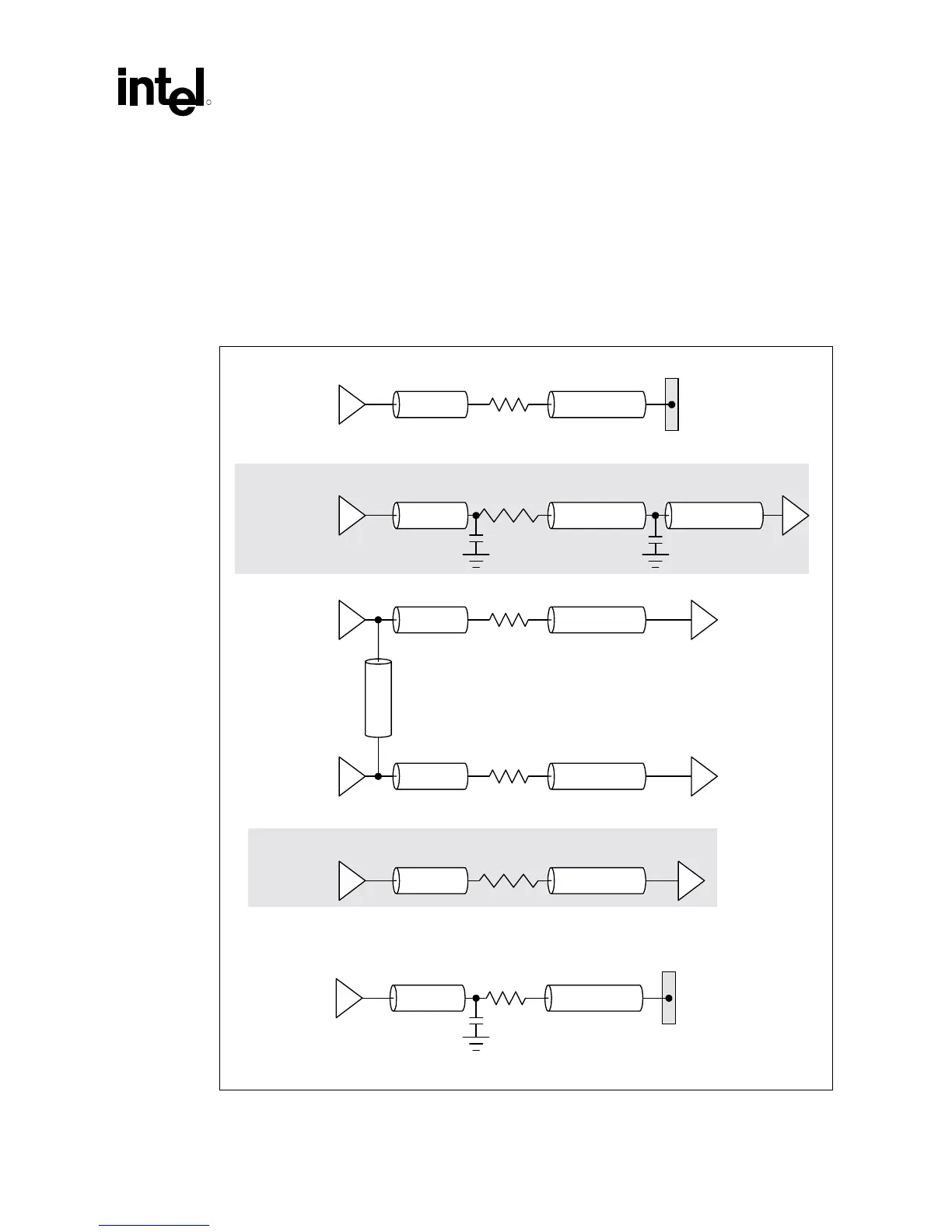
11.3 Clock Routing Guidelines
This section presents the generic clock routing guidelines for both 2-DIMM and 3-DIMM boards.
For 3-DIMM boards, additional analysis must be performed by the motherboard designer to ensure
that the clocks generated by the external PCI clock buffer meet the PCI specifications for clock
skew at the receiver, when compared with the PCI clock at the ICH.
Figure 70. Clock Routing Topologies
CK815
Section 1 Section 2
Layout 1
33
Ω
Connector
CK815
Section 1 Section 2
Layout 3
33
Ω
CK815
Section 1 Section 3
33
Ω
Section 0
Processor
GMCH
clk_routing_topo
CK815
Section 1 Section 2
Layout 4
33
Ω
CK815
Section 1 Section 2
Layout 2
33
Ω
Section 3
22 pF10 pF
CK815
Section 1 Section 2
Layout 5
33
Ω
Connector
22 pF