System Bus Design Guidelines
R
46 Intel
®
815 Chipset Platform Design Guide
5.2 General Topology and Layout Guidelines
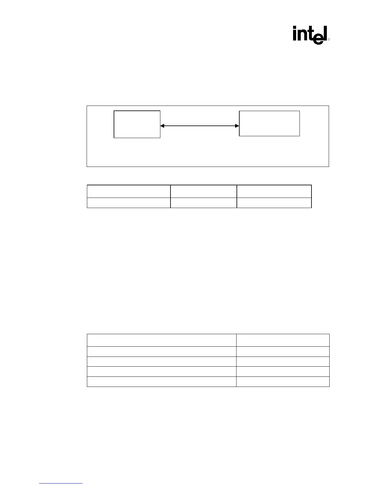
Figure 19. Topology for 370-Pin Socket Designs with Single-Ended Termination (SET)
sys_bus_topo_PGA370
GMCH
PGA370 socket
L(1): Z
0
= 60 Ω ± 15%
Table 9. Trace Guidelines for Figure 19
1, 2, 3
Description Min. Length (inches) Max. Length (inches)
GMCH to PGA370 socket trace 1.90 4.50
NOTES:
1. All AGTL/AGTL+ bus signals should be referenced to the ground plane for the entire route.
2. Use an intragroup AGTL/AGTL+ spacing : line width : dielectric thickness ratio of at least 2:1:1 for
microstrip geometry. If
ε
r
= 4.5, this should limit coupling to 3.4%. For example, intragroup AGTL+
routing could use 10-mil spacing, 5-mil traces, and a 5-mil prepreg between the signal layer and the
plane it references (assuming a 4-layer motherboard design).
3. The recommended trace width is 5 mils, but not greater than 6 mils.
Table 10 contains the trace width space ratios assumed for this topology. Three types of cross-talk
are considered in this guideline: Intragroup AGTL/AGTL+, Intergroup AGTL/AGTL+, and
AGTL/AGTL+ to non-AGTL/AGTL+. Intragroup AGTL/AGTL+ cross-talk involves interference
between AGTL/AGTL+ signals within the same group. Intergroup AGTL/AGTL+ cross-talk
involves interference from AGTL/AGTL+ signals in a particular group to AGTL/AGTL+ signals
in a different group. An example of AGTL/AGTL+ to non-AGTL/AGTL+ cross-talk is when
CMOS and AGTL/AGTL+ signals interfere with each other. The AGTL/AGTL+ signals consist of
the following groups: data signals, control signals, clock signals, and address signals.
Table 10. Trace Width:Space Guidelines
Cross-Talk Type Trace Width:Space Ratios
1, 2
Intragroup AGTL/AGTL+ signals (same group AGTL/AGTL+) 5:10 or 6:12
Intergroup AGTL/AGTL+ signals (different group AGTL/AGTL+) 5:15 or 6:18
AGTL/AGTL+ to System Memory Signals 5:30 or 6:36
AGTL/AGTL+ to non-AGTL/AGTL+ 5:25 or 6:24
NOTES:
1. Edge-to-edge spacing.
2. Units are in mils.