I/O Subsystem
R
126 Intel
®
815 Chipset Platform Design Guide
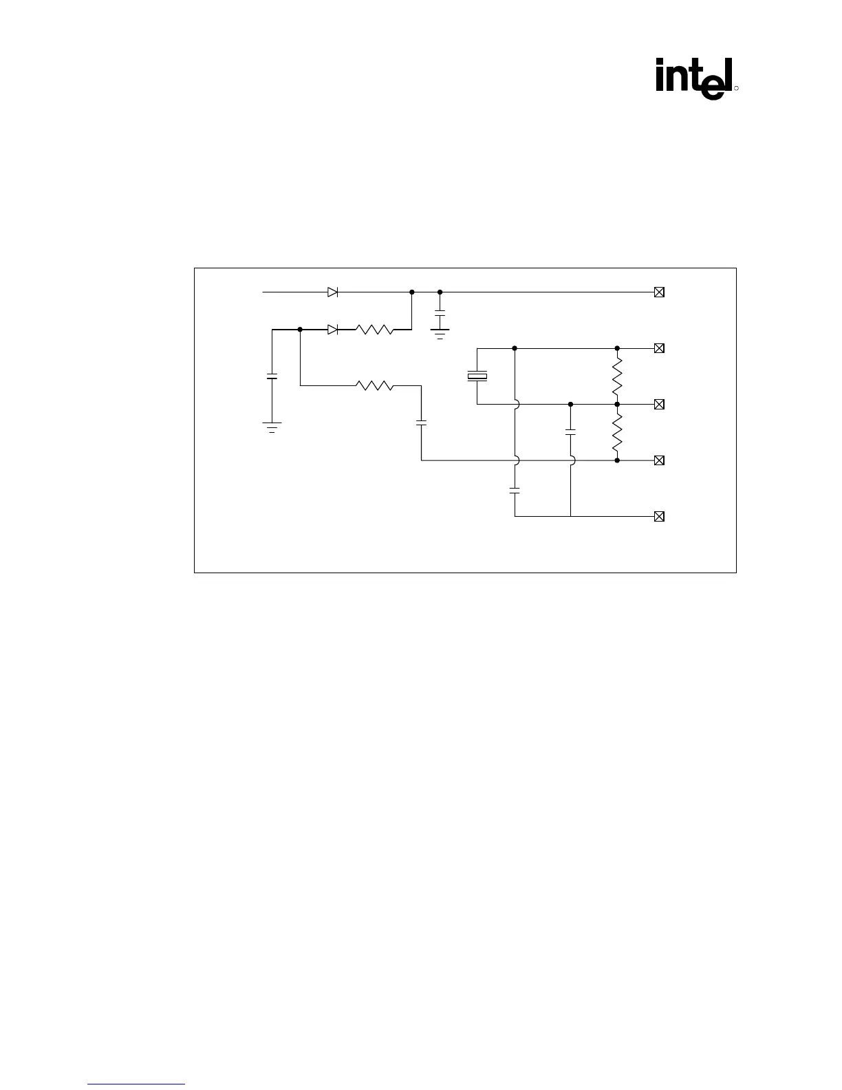
10.9.1 RTC Crystal
The ICH RTC module requires an external oscillating source of 32.768 kHz connected on the
RTCX1 and RTCX2 pins.
Figure 65. External Circuitry of RTC Oscillator
C3
18 pF
3.3 V
VCCSUS
1 k
Ω
Vbatt
1 k
Ω
C1
0.047 µF
32768 Hz
Xtal
R1
10 M
Ω
R2
10 M
Ω
C2
18 pF
1
µ
F
VCCRTC
2
RTCX2
3
RTCX1
4
VBIAS
5
VSSRTC
6
RTC_osc_circ
1
1
NOTES:
1. The exact capacitor value should be based on the crystal vendor’s recommendations.
2. VCCRTC: Power for RTC well
3. RTCX2: Crystal input 2 – Connected to the 32.768 kHz crystal
4. RTCX1: Crystal input 1 – Connected to the 32.768 kHz crystal
5. VBIAS: RTC bias voltage – This pin is used to provide a reference voltage. This DC voltage sets a
current, which is mirrored through the oscillator and buffer circuitry.
6. VSS: Ground
10.9.2 External Capacitors
To maintain RTC accuracy the external capacitor C1 must be 0.047 µF. The external capacitor
values for C2 and C3 should be chosen to provide the manufacturer-specified load capacitance
(Cload) for the crystal when combined with the parasitic capacitance of the trace, socket (if used),
and package. When the external capacitor values are combined with the capacitance of the trace,
socket, and package, the closer the capacitor value can be matched to the actual load capacitance
of the crystal used, the more accurate will be the RTC.
The following equation can be used to choose the external capacitance values (C2 and C3):
Cload = (C2 * C3) / (C2 + C3) + Cparasitic
C3 can be chosen such that C3 > C2. Then C2 can be trimmed to obtain 32.768 kHz.