I/O Subsystem
R
Intel
®
815 Chipset Platform Design Guide 115
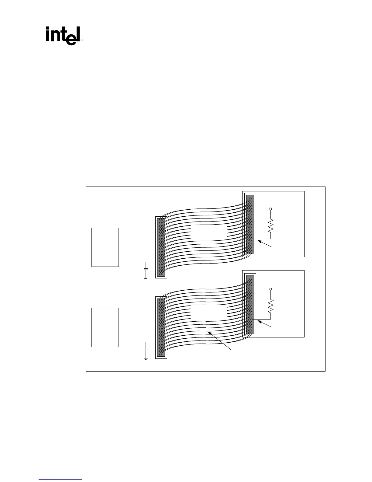
10.2.2 Device Side Cable Detection
BIOS Queries IDE Device for Cable Type
Device-side detection requires only a 0.047 µF capacitor on the motherboard, as shown in
Figure 59. This mechanism creates a resistor-capacitor (RC) time constant. The ATA mode 3 or 4
device will drive PDIAG#/CBLID# low and then release it (pulled up through a 10 kΩ resistor).
The device will sample the PDIAG# signal after releasing it. In an 80-conductor cable,
PDIAG#/CBLID# is not connected through; therefore, the capacitor has no effect. In a
40-conductor cable, PDIAG#/CBLID# is connected through to the device; therefore, the signal
will rise more slowly. The device can detect the difference in rise times and it will report the cable
type to the BIOS when it sends the IDENTIFY_DEVICE packet during system boot, as described
in the ATA/66 specification.
Figure 59. Drive-Side IDE Cable Detection
40-conductor
cable
IDE Drive
10 k
Ω
5 V
PDIAG
ICH
0.047 µF
IDE Drive
10 k
Ω
5 V
PDIAG
ICH
Open
0.047 µF
80-conductor
IDE cable
iDE_cable_det_drive