Universal Socket 370 Design
R
Intel
®
815 Chipset Platform Design Guide 33
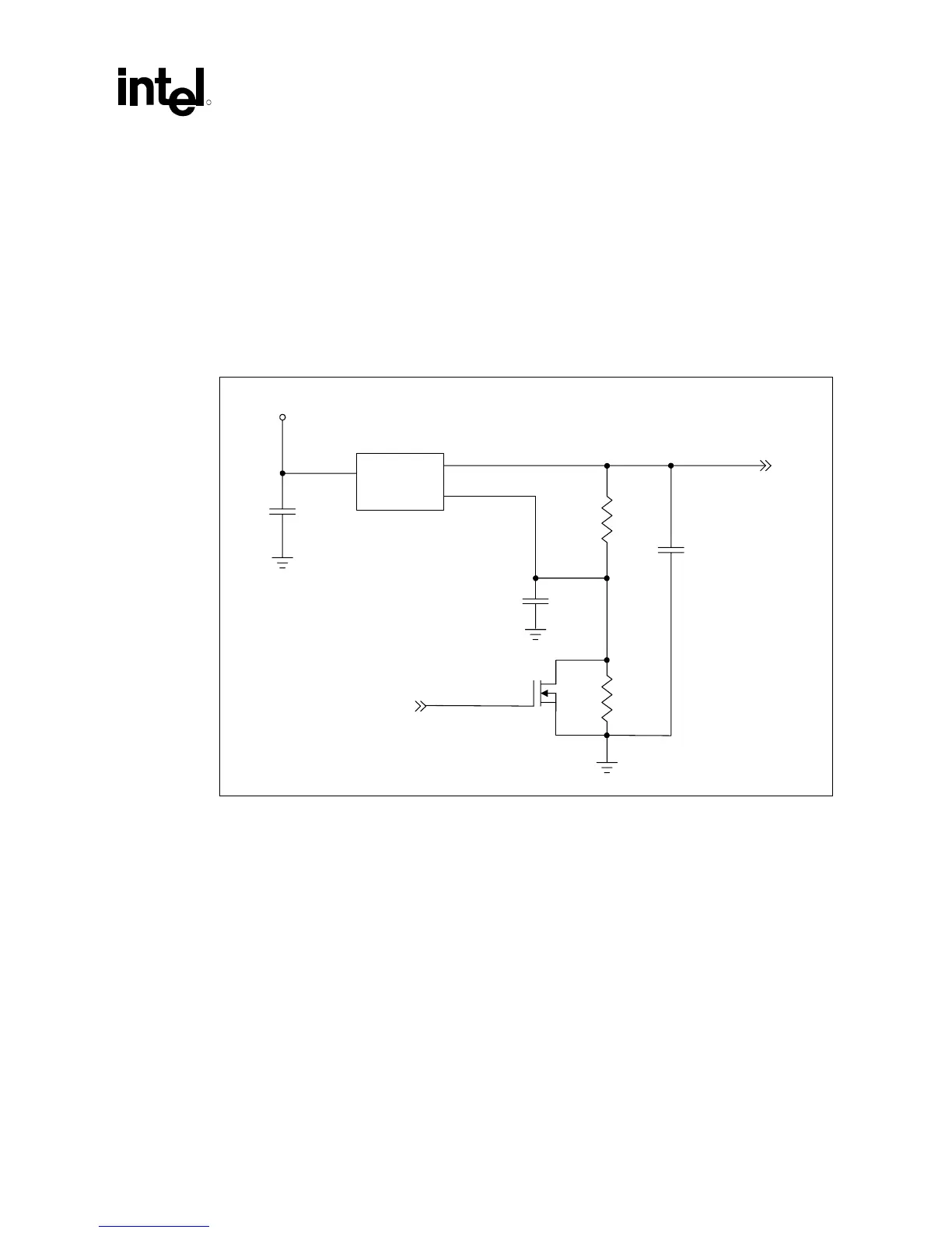
4.2.3 Setting the Appropriate Processor VTT Level
Because the Pentium III processor (CPUID=068xh) / Celeron processor (CPUID=068xh), and
future 0.13 micron socket 370 processors require different VTT levels, the platform must be able
to provide the appropriate voltage level after determining which processor is in the socket.
Referring to Figure 9, the TUAL5 reference schematic signal serves to control the FET, and by
doing so determines whether the voltage regulator supplies 1.25V or 1.5V to VTT for AGTL or
AGTL+, respectively.
Figure 9. VTT
Selection Switch
Vin
Vout
ADJ
VCC3_3
10
µF
LT1587-ADJ
TUAL5
MOSFET N
10
Ω
1%
49.9
Ω
1%
0.1
µF
22
µF
Tantalum
VTT
Vtt_Sel_Sw