System Design Checklist
R
166 Intel
®
815 Chipset Platform Design Guide
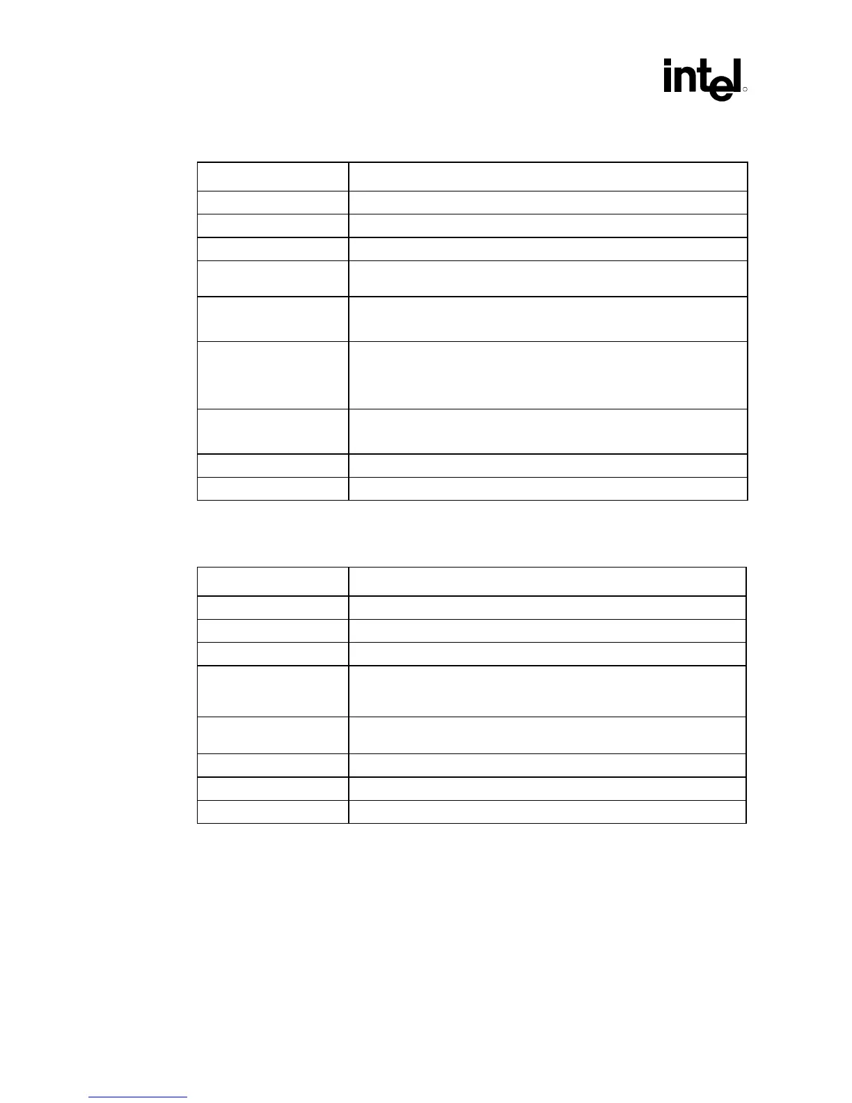
13.6 System Checklist
Checklist Items Recommendations
KEYLOCK# • Pull-up through 10 kΩ resistor to VCC3_3
PBTN_IN • Connects to PBSwitch and PBin.
PWRLED • Pull-up through a 220 Ω resistor to VCC5
R_IRTX • Signal IRTX after it is pulled down through4.7 kΩ resistor to GND and
passes through 82 Ω resistor
IRRX • Pull-up to 100 kΩ resistor to VCC3_3
• When signal is input for SI/O Decouple through 470 pF capacitor to GND
IRTX • Pull-down through 4.7 kΩ to GND
• Signal passes through 82 Ω resistor
• When signal is input to SI/O Decouple through 470 pF capacitor to GND
FP_PD • Decouple through a 470 pF capacitor to GND
• Pull-up 470 Ω to VCC5
PWM1, PWM2 • Pull-up through a 4.7 kΩ resistor to VCC3_3
INTRUDER# • Pull signal to VCCRTC (VBAT), if not needed.
13.7 FWH Checklist
Checklist Items Recommendations
No floating inputs • Unused FGPI pins need to be tied to a valid logic level.
WPROT, TBLK_LCK • Pull-up through a 4.7 kΩ to VCC3_3
R_VPP • Pulled up to VCC3_3, decoupled with two 0.1 µF capacitors to GND.
FGPI0_PD, FGPI1_PD,
FGPI2_PD, FPGI3_PD,
FPGI4_PD, IC_PD
• Pull-down through a 8.2 kΩ resistor to GND
FWH_ID1, FWH_ID2,
FWH_ID3
• Pull-down to GND
INIT# • FWH INIT# must be connected to processor INIT#.
RST# • FWH RST# must be connected to PCIRST#.
ID[3:0] • For a system with only one FWH device, tie ID[3:0] to ground.