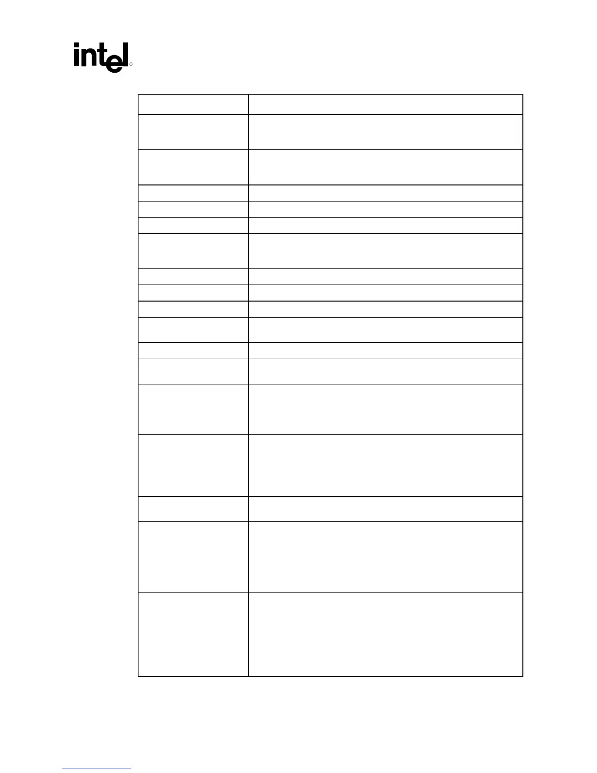
System Design Checklist
R
Intel
®
815 Chipset Platform Design Guide 157
Checklist Items Recommendations
CLKREF • Connect to divider on VCC2.5 or VCC3.3 to create 1.25V reference with
a 4.7
µF decoupling capacitor. Resistor divider must be created from 1%
tolerance resistors. Do not use VTT as source voltage for this reference!
CPUPRES# • Tie to ground. Leave as No Connect or connect to PWRGOOD logic to
gate system from powering on if no processor is present. If used, 1 k
Ω
to 10 k
Ω pull-up resistor to VCC
CMOS
.
DYN_OE • 1 kΩ pull-up resistor to VTT.
PICCLK • See Section 10.5.
PICD[1:0] • 150 Ω pull-up resistor to VCC
CMOS
/Connect to ICH.
PLL1, PLL2 • Low-pass filter on VCC
CORE
provided on motherboard. Typically a 4.7 µH
inductor in series with VCC
CORE
is connected to PLL1, and then through
a series 33
µF capacitor to PLL2.
RTTCTRL
5
(S35) • 56 Ω ± 1% pull-down resistor to ground.
SLEWCTRL (E27) • 110 Ω ± 1% pull-down resistor to ground.
STPCLK# (AG35) • Connect to ICH.
THERMDN, THERMDP • No Connect if not used. Otherwise, connect to thermal sensor using
vendor guidelines.
VCC2.5 • No connect for Intel
®
Pentium
®
III processors
GTL_REF/VCMOS_REF
(AK22)
• Connect to a 1.0V voltage divider derived from VCC
CMOS
. See Section
4.2.7.
VCC
CORE
• 16 ea. (minimum) 4.7 µF in 1206 package all placed within the PGA370
socket cavity.
• 8 ea. (minimum) 1 µF in 0612 package placed in the PGA370 socket
cavity.
VID[25mV, 3:0] • Connect to on-board VR or VRM. 25mV should connect to VID25mV.
For on-board VR, 10 k
Ω pull-up resistor to power solution-compatible
voltage is required (usually pulled up to input voltage of the VR). Some
of these solutions have internal pull-ups. Optional override (jumpers,
ASIC, etc.) could be used. May also connect to system monitoring
device.
VTTPWRGD • Pull-up to VTT through 1 kΩ resistor and connect to VTTPWRGD
circuitry. See Section 4.2.6.
VREF [6:0] • Connect to VREF voltage divider made up of 75 Ω and 150 Ω 1%
resistors connected to VTT. Processor VREF must be able to be
separate from chipset VREF.
• Decoupling Guidelines:
4 ea. (minimum) 0.1 µF in 0603 package placed within 500 mils of
VREF pins
VTT • Connect AH20, AK16, AL13, AL21, AN11, AN15, G35, G37, AD36,
AB36, X34, AA33, AA35, AN21, E23, S33, S37, U35, and U37 to VRM
8.5-compliant regulator. Provide high- and low-frequency decoupling.
• Decoupling Guidelines:
20 ea (minimum) 0.1 µF in 0603 package placed as near the VTT
processor pins as possible.
4 ea (minimum) 0.47 µF in 0612 package