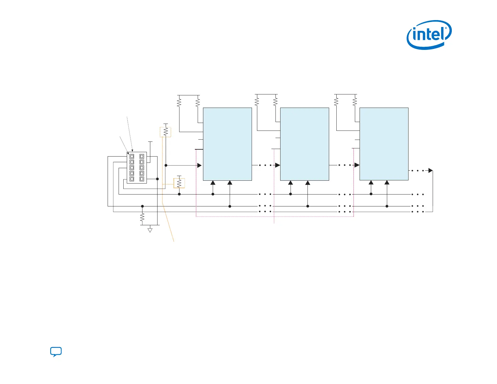
3.4.3.1. JTAG Multi-Device Configuration using Download Cable
Figure 52. Connection Setup for JTAG Multi Device Configuration using Download Cable
Pin 1
1 kΩ
10 kΩ
TMS TCK
TDI
TDO
nSTATUS
nCONFIG
MSEL[2:0]
CONF_DONE
TMS TCK
TDI
TDO
nSTATUS
nCONFIG
MSEL[2:0]
CONF_DONE
Intel FPGA Intel FPGA Intel FPGA
TMS TCK
TDI
TDO
nSTATUS
nCONFIG
MSEL[2:0]
CONF_DONE
Download cable
10-pin male header
(JTAG mode)
Resistor values can vary between 1 kΩ to 10 kΩ.
Perform signal integrity to select the resistor
value for your setup.
For JTAG configuration only:
Connect MSEL [2:0] of Intel FPGA devices to VCCIO_SDM through 4.7 kΩ external pull-up resistor.
For JTAG in conjunction with another configuration scheme:
Connect MSEL [2:0] of Intel FPGA devices based on the non-JTAG configuration scheme.
GND
V
CCIO_SDM
V
CCIO_SDM
V
CCIO_SDM
V
CCIO_SDM
10 kΩ
10 kΩ
V
CCIO_SDM
10 kΩ
10 kΩ
V
CCIO_SDM
10 kΩ
3.4.4. Debugging Guidelines for the JTAG Configuration Scheme
The JTAG configuration scheme overrides all other configuration schemes. The SDM is always ready to accept configuration
over JTAG unless a security feature disables the JTAG interface. JTAG is particularly useful in recovering a device that may be
in an unrecoverable state reached when trying to configure using a corrupted image.
3. Intel Agilex Configuration Schemes
UG-20205 | 2019.10.09
Send Feedback
Intel
®
Agilex
™
Configuration User Guide
119