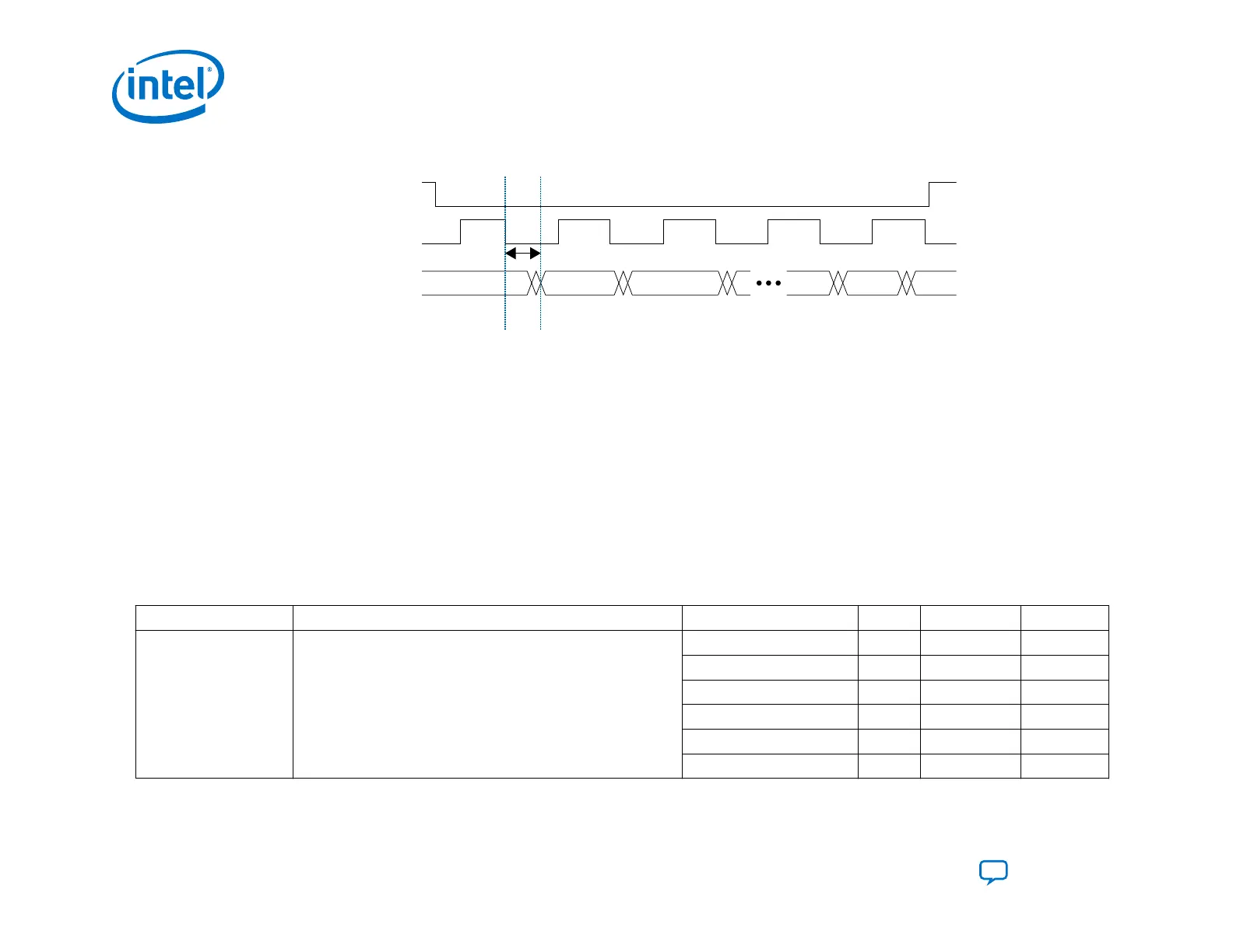
Figure 38. AS Configuration Serial Input Timing Diagram
nCSO
AS_CLK
AS_DATA IN0 IN1 INn
T
ext_delay
Note: For more information about the timing parameters, refer to the Intel Agilex Device Datasheet.
3.2.5. Maximum Allowable External AS_DATA Pin Skew Delay Guidelines
You must minimize the skew on the AS data pins.
Skew delay includes the following elements:
• The delay due to the differences in board traces lengths on the PCB
• The capacitance loading of the flash device
The table below lists the maximum allowable skew delay depending on the AS_CLK frequency. Intel recommends that you to
perform IBIS simulations to ensure that the skew delay does not exceed the maximum delay specified in this table.
Table 27. Maximum Skew for AS Data Pins in Nanoseconds (ns)
Symbol Description Frequency Min Typical Max
T
ext_skew
Skew delay for AS_DATA for the AS_CLK frequency specified
133 MHz — — 3.60
125 MHz — — 4.00
115 MHz — — 4.20
108 MHz — — 4.60
100 MHz — — 5.0
<100 MHz — — 5.0
3. Intel Agilex Configuration Schemes
UG-20205 | 2019.10.09
Intel
®
Agilex
™
Configuration User Guide
Send Feedback
94