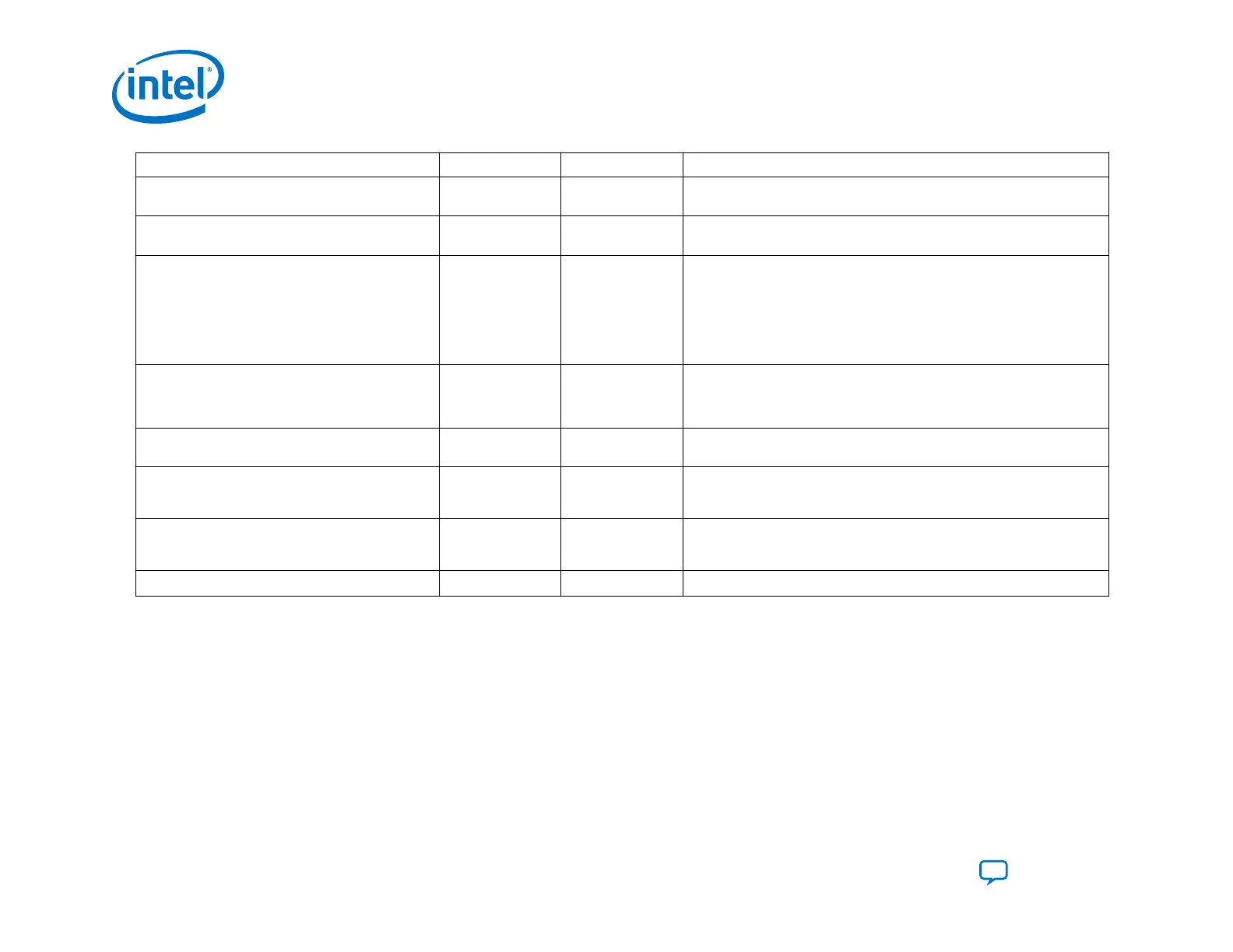
Pin Type Weak Pull-Up Function
flash_nwe
Output —
Connects to the nWE pin of the flash memory device. When low enables
write operations to the flash memory device.
flash_noe
Output —
Connects to the nOE pin of the flash memory device. When low enables
the outputs of the flash memory device during a read operation.
flash_clk
Output —
For burst mode. Connects to the CLK input pin of the flash memory
device. The active edges of CLK increment the flash memory device
internal address counter. The flash_clk frequency is half of the
pfl_clk frequency in burst mode for a single CFI flash. In dual CFI flash
solution, the flash_clk frequency runs at a quarter of the pfl_clk
frequency. Use this pin for burst mode only. Do not connect these pins
from the flash memory device to the host if you are not using burst mode.
flash_nadv
Output — For burst mode. Connects to the address valid input pin of the flash
memory device. Use this signal to latch the start address. Use this pin for
burst mode only. Do not connect these pins from the flash memory device
to the host if you are not using burst mode.
flash_nreset
Output — Connects to the reset pin of the flash memory device. A low signal resets
the flash memory device.
fpga_nconfig
Open Drain Output 10-kW Pull-Up
Resistor
Connects to the nCONFIG pin of the FPGA. A low pulse resets the FPGA
and initiates configuration. These pins are not available for the flash
programming option in the PFL II IP core.
(7)
pfl_reset_watchdog
Input — A switch signal to reset the watchdog timer before the watchdog timer
times out. To reset the watchdog timer hold the signal high or low for at
least two pfl_clk clock cycles.
pfl_watchdog_error
Output — When high indicates an error condition to the watchdog timer.
Related Information
Avalon Interface Specifications
3.2. AS Configuration
In AS configuration schemes, the SDM block in the Intel Agilex device controls the configuration process and interfaces. The
serial flash configuration device stores the configuration data. During AS Configuration, the SDM first powers on with the boot
ROM. Then, the SDM loads the initial configuration firmware from AS x4 flash. After the configuration firmware loads, this
firmware controls the remainder of the configuration process, including I/O configuration and FPGA core configuration.
Designs including an HPS, can use the HPS to access serial flash memory after the initial configuration.
3. Intel Agilex Configuration Schemes
UG-20205 | 2019.10.09
Intel
®
Agilex
™
Configuration User Guide
Send Feedback
86