Note: The serial flash configuration device must be fully powered up at the same time or before ramping up V
CCIO_SDM
of the Intel
Agilex device.
The AS configuration scheme supports AS x4 (4-bit data width) mode only.
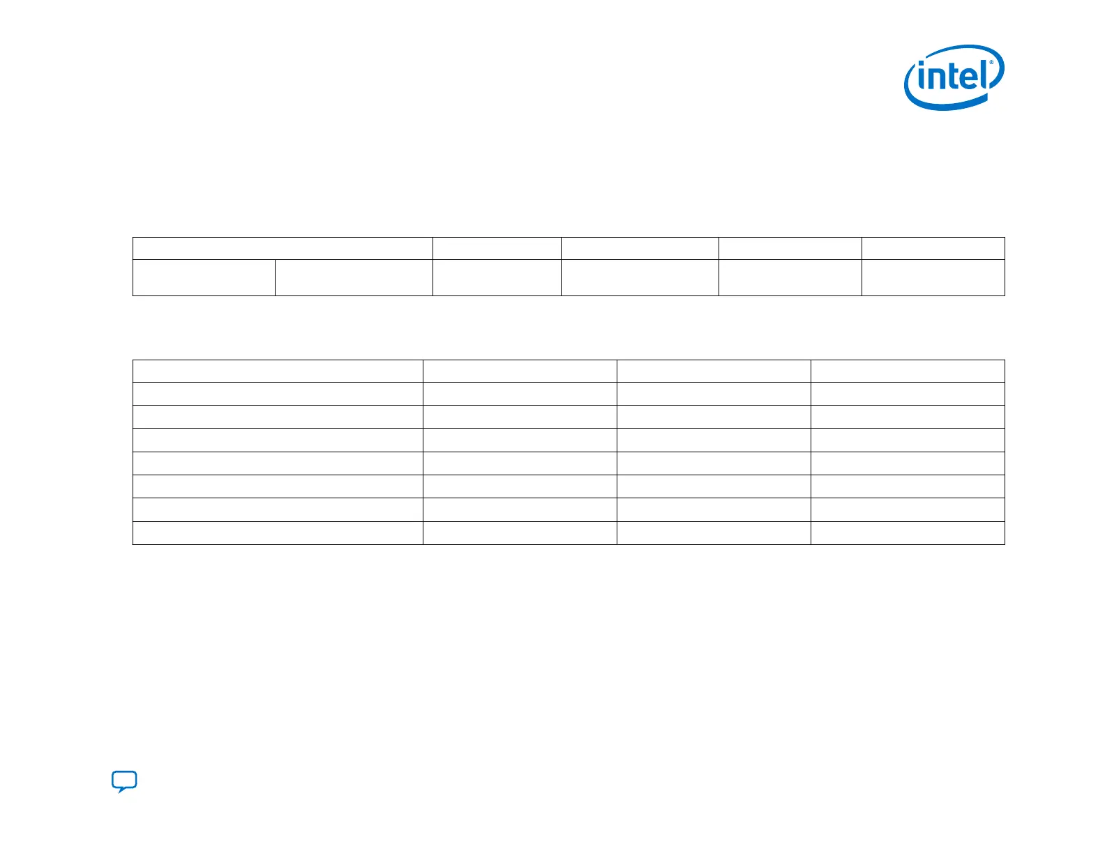
Table 23. Intel Agilex Configuration Data Width, Clock Rates, and Data Rates
Mode Data Width (bits) Max Clock Rate Max Data Rate MSEL[2:0]
Active Active Serial (AS) 4 133 MHz 532 Mb
Fast mode - 001
Normal mode - 011
Table 24. Required Configuration Signals for the AS Configuration Scheme
You specify SDM I/O pin functions using the Device ➤ Configuration ➤ Device and Pin Options dialog box in the Intel Quartus Prime software. You can
reassign the GPIO, dual-purpose configuration pins for other functions in user mode.
Configuration Function Pin Type Direction Powered by
nSTATUS
SDM I/O Output V
CCIO_SDM
nCONFIG
SDM I/O Input V
CCIO_SDM
MSEL[2:0]
SDM I/O, Dual-Purpose Input V
CCIO_SDM
CONF_DONE
SDM I/O Output V
CCIO_SDM
AS_nCSO[3:0]
SDM I/O Output V
CCIO_SDM
AS_DATA[3:0]
SDM I/O Bidirectional V
CCIO_SDM
AS_CLK
SDM I/O Output V
CCIO_SDM
Note:
Although the CONF_DONE and INIT_DONE configuration signals are not required, Intel recommends that you use these
signals. The SDM drives the CONF_DONE signal high after successfully receiving full bitstream. The SDM drives the
INIT_DONE signal high to indicate the device is fully in user mode.These signals are important when debugging configuration.
You can reassign the GPIO, dual-purpose configuration pins for other functions in user mode.
MSEL Pin Function for the AS x4 Configuration Scheme
The SDM samples the MSEL pins immediately after power-on in the SDM Start state. After the SDM samples the MSEL pins,
the MSEL pins become active-low chips selects. For AS x4 designs using one flash device, AS_nCSO asserts low. The
remaining chip select pins, AS_nCS1 - AS_nCS3 deassert high.
3. Intel Agilex Configuration Schemes
UG-20205 | 2019.10.09
Send Feedback
Intel
®
Agilex
™
Configuration User Guide
87