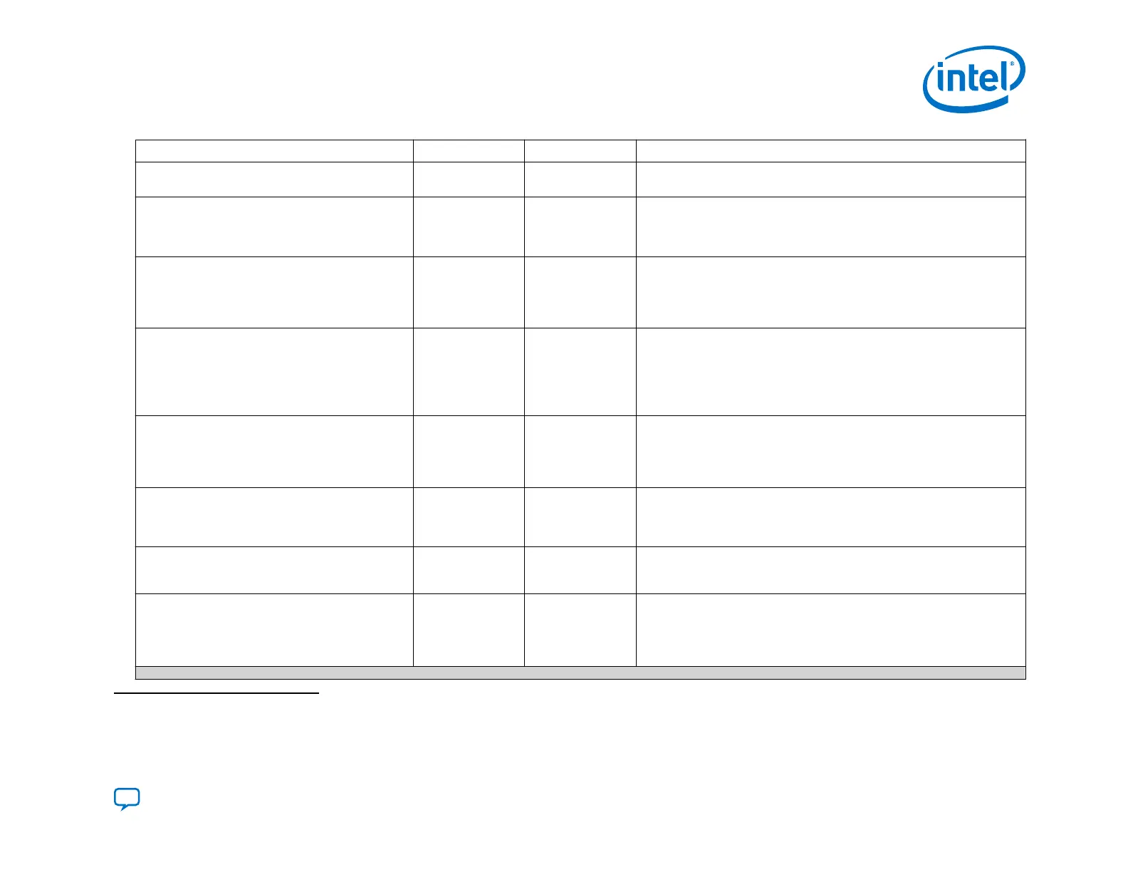
Pin Type Weak Pull-Up Function
fpga_pgm[]
Input — Determines the page for the configuration. This pin is not available if you
are only using the PFL II IP for flash programming.
fpga_conf_done
Input 10 kΩ Pull-Up
Resistor
Connects to the CONF_DONE pin of the FPGA. The FPGA releases the pin
high if the configuration is successful. During FPGA configuration, this pin
remains low. This pin is not available if you are only using the PFL II IP for
flash programming.
fpga_nstatus
Input 10 kΩ Pull-Up
Resistor
Connects to the nSTATUS pin of the FPGA. This pin is high before the
FPGA configuration begins and must stay high during FPGA configuration.
If a configuration error occurs, the FPGA pulls this pin low and the PFL II
IP core stops reading the data from the flash memory device. This pin is
not available if you are only using the PFL II IP for flash programming.
pfl_nreconfigure
Input — When low initiates FPGA reconfiguration. To implement manual control of
reconfiguration connect this pin to a switch. You can use this input to write
your own logic in a CPLD to trigger reconfiguration via the PFL II IP. You
can use pfl_nreconfigure to drive the fpga_nconfig output signal
initiating reconfiguration. The pfl_clk pin registers this signal. This pin is
not available if you are only using the PFL II IP for flash programming.
pfl_flash_access_request
Output — For system-level synchronization. When necessary, this pin connects to a
processor or an arbiter. The PFL II IP core drives this pin high when the
JTAG interface accesses the flash or the PFL II IP configures the FPGA.
This output pin works in conjunction with the flash_noe and flash_nwe
pins.
flash_addr[]
Output — The flash memory address. The width of the address bus depends on the
density of the flash memory device and the width of the flash_data bus.
Intel recommends that you turn On the Set flash bus pins to tri-state
when not in use option in the PFL II .
flash_data[]
Input or Output
(bidirectional pin)
— Bidirectional data bus to transmit or receive 8-, 16-, or 32-bit data. Intel
recommends that you turn On the Set flash bus pins to tri-state when
not in use option in the PFL II.
(7)
flash_nce[]
Output —
Connects to the nCE pin of the flash memory device. A low signal enables
the flash memory device. Use this bus for multiple flash memory device
support. The flash_nce pin connects to each nCE pin of all the
connected flash memory devices. The width of this port depends on the
number of flash memory devices in the chain.
continued...
(7)
Intel recommends that you do not insert logic between the PFL II pins and the host I/O pins, especially on the flash_data and
fpga_nconfig pins.
3. Intel Agilex Configuration Schemes
UG-20205 | 2019.10.09
Send Feedback
Intel
®
Agilex
™
Configuration User Guide
85