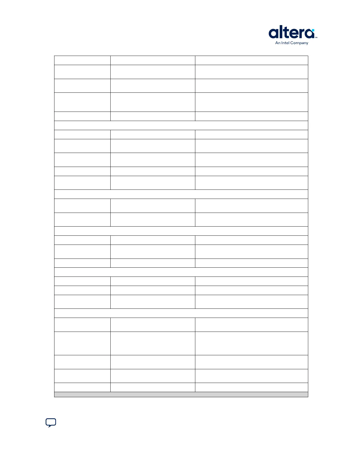
Board Reference Type Description
SW2 DIP configuration and user switch SW2 Includes switches to control boot images, JTAG
bypass and HSMC bypass.
J7 Jumper for the MAX 10 ADC Connects potentiometer for providing adjustable
voltage to the ADC.
S5
Pulse_nconfig push button Emulates pulsing the nCONFIG pin low to trigger
reconfiguration even though the physical pin is
unaffected.
S6 CPU reset push button Default reset for the FPGA logic.
Status Elements
D1 Blue power LED Illuminates when 12-V power is present.
D2 Green high-speed mezzanine card
(HSMC) LED
Illuminates when the HSMC is present.
D13, D14 Green USB-UART LEDs Illuminates when the USB-UART transmitter and
receiver are in use.
D20 Configuration done LED Illuminates when the FPGA is configured.
D21, D22, D23 Power LEDs Indicates that 3.3 V, 2.5 V, 1.2 V are powered up
successfully.
Clock Circuitry
X1 Programmable Clock for ADC Programmable oscillator for ADC with default
frequency of 10 MHz.
U2 Programmable Clock Four channel programmable oscillator with default
frequencies of 25, 50, 100, and 125 MHz.
General User Input/Output
S1, S2, S3, S4 General user push buttons Four user push buttons. Driven low when pressed.
D15, D16, D17, D18,
D19
User LEDs Four user LEDs. Illuminates when driven low.
SW1, SW2.1 User DIP switches Quad user DIP switches.
Memory Devices
U5 DDR3 SDRAM A memory 64 Mx16.
U6 DDR3 SDRAM B memory 128 Mx8.
U7 Quad serial peripheral interface (quad
SPI) flash
512 Mb.
Communication Ports
J2 HSMC port Provides 84 CMOS or 17 LVDS channels per HSMC
specification.
U9, U10 Two Gigabit Ethernet ports
• Ethernet A (Bottom)
• Ethernet B (Top)
RJ-45 connector which provides a 10/100/1000
Ethernet connection via a Marvell 88E1111 x 2 PHY
and the FPGA-based Triple Speed Ethernet Intel
FPGA IP function in RGMII mode.
J4, J5 Two Diligent Pmod* connectors 12-pin interface with 8 I/O signal pins used to
connect low frequency, low I/O peripheral modules.
J11 Mini-USB 2.0 UART port USB connector with USB-to-UART bridge for serial
UART interface
J12 Mini-USB port Embedded Intel FPGA Download Cable II.
continued...
A. Development Kit Components
683460 | 2024.11.20
Send Feedback
MAX
®
10 FPGA Development Kit User Guide
35