EasyManua.ls Logo

INVT GD300L Series User Manual

INVT GD300L Series
174 pages
To Next Page IconTo Next Page
To Previous Page IconTo Previous Page
Page #133 background imageLoading...
Page #133 background image
Goodrive300-LIFT series inverter Communication protocol
-129-
Code
Name
Meaning
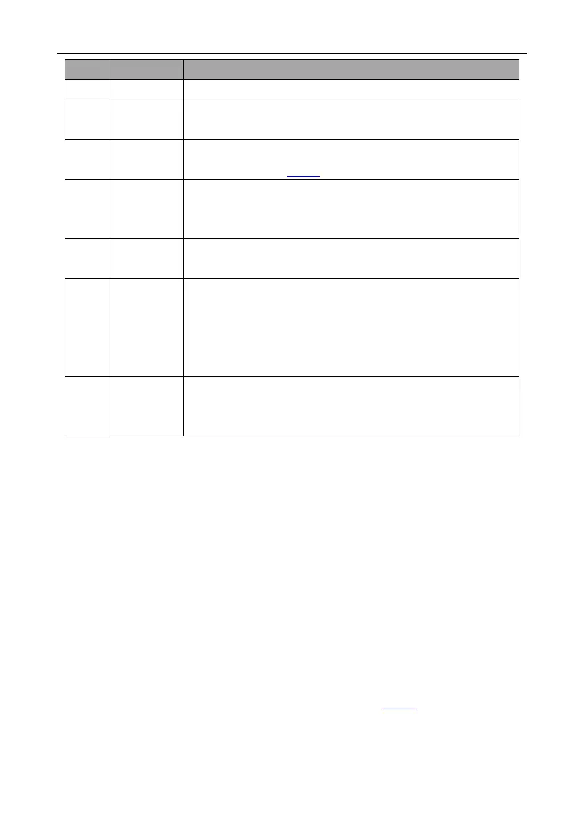
the range, but indicate the message frame is an illegal frame.
04H
Operation
failed
The parameter setting in parameter writing is invalid. For example,
the function input terminal cannot be set repeatedly.
05H
Password
error
The password written to the password check address is not same as
the password set by P07.00.
06H
Data frame
error
In the frame message sent by the upper monitor, the length of the
digital frame is incorrect or the counting of CRC check bit in RTU is
different from the lower monitor.
07H
Parameters
only for read
It only happen in write command
08H
Parameters
cannot be
changed
during
running
The modified parameter in the writing of the upper monitor cannot be
modified during running.
09H
Password
protection
When the upper monitor is writing or reading and the user password
is set without password unlocking, it will report that the system is
locked.
The slave uses functional code fields and fault addresses to indicate it is a normal response or some
error occurs (named as objection response). For normal responses, the slave shows corresponding
function codes, digital address or sub-function codes as the response. For objection responses, the
slave returns a code which equals the normal code, but the first byte is logic 1.
For example: when the master sends a message to the slave, requiring it to read a group of address
data of the inverter function codes, there will be following function codes:
0 0 0 0 0 0 1 1 (Hex 03H)
For normal responses, the slave responds the same codes, while for objection responses, it will
return:
1 0 0 0 0 0 1 1 (Hex 83H)
Besides the function codes modification for the objection fault, the slave will respond a byte of
abnormal code which defines the error reason.
When the master receives the response for the objection, in a typical processing, it will send the
message again or modify the corresponding order.
For example, set the "running command channel" of the inverter (P00.01, parameter address is
0001H) with the address of 01H to 03, the command is as following:

Table of Contents

Question and Answer IconNeed help?

Do you have a question about the INVT GD300L Series and is the answer not in the manual?

INVT GD300L Series Specifications

General IconGeneral
Storage Temperature-20°C ~ +60°C
Output Voltage0 ~ Input Voltage
Output Power0.75kW~630kW
Efficiency≥98%
Cooling MethodForced air cooling
Protection LevelIP20
Communication ProtocolModbus, CANopen, PROFIBUS
Control ModeV/F control
Overload Capacity150% for 60s
BrakingBuilt-in braking unit or external braking resistor
Protection FeaturesOvervoltage, undervoltage, overcurrent, short circuit, overheating, phase loss
Humidity5%~95% (non-condensing)
Altitude≤1000m (derating above 1000m)
Ambient Temperature-10°C ~ +50°C (derating above 40°C)

Summary

Safety Precautions

Precautions for Quick Application

Basic Commissioning

Outlines the essential steps for initial setup and commissioning of the inverter.

Installation Guide

Mechanical Installation and Environment

Covers mechanical installation requirements and environmental conditions for the inverter.

Wiring

Main Circuit Wiring

Details the connections for the main power input and output terminals.

Control Circuit Wiring

Explains the wiring diagrams and terminal connections for the control circuit.

Wiring Protection

Short-Circuit and Overload Protection

Covers methods for protecting the inverter and cables from short circuits and overloads.

Keypad Operation

Parameter Modification and Password

Explains how to modify function codes and set up password protection.

Function Parameters

Communication and Protection Parameters

Details parameters for serial/CAN communication and protective functions.

Commissioning Guidelines

Debugging Running Modes

Covers autotuning, S-curve adjustment, and comfortability settings.

Fault Tracking

Fault Identification and Reset

Explains how to identify, reset, and view fault history.

Inverter Faults and Solutions

Lists common inverter faults, their possible causes, and recommended solutions.

Common Fault Analysis

Provides troubleshooting flowcharts for common issues like motor problems and overvoltage.

Communication Protocol

Appendix A Expansion Cards

STO Instructions

Details the Safe Torque Off (STO) function, its logic, and installation checklist.

Related product manuals