Functionality
USER MANUAL FPC 200 - 3/2017 15
2.1 Protections in general
Within this chapter the general theory of protection functions is described. For clear understanding several time
characteristics for different scenarios are presented.
Default values
Default values are presented as bold.
Example:
Minimum value of pickup delay is 0 ms, maximum
value is 1000 ms. Default value is set to 5 ms.
Table 2 Example of default parameter setting.
Protection operation range
Fault is detected when monitored value exceeds the
chosen threshold (pickup value). At that point the
protection enters into protection operation range or
fault area. To prevent unwanted switching a hysteresis
characteristic is introduced. Drop-out value is set
relative to pickup value.
When the monitored value enters the protection
operating range the protections picks up. On the other
hand when the value falls below the operating range the
protection drops or resets.
Protection operation range is shown on Figure 2.1.
Pickup value
Drop-out value
Fault detection
Monitored value
Fault area
Figure 2.1: Protection operation range - fault area.
Example: Nominal current of protected element I
n_obj
is
set to 300 A, pickup value is set to 1,1 I
n_obj
and Drop-out
is 0,95 I
p
. The protection will pick up when current
exceeds 330 A. It will drop out when the current drops
below 313,5 A.
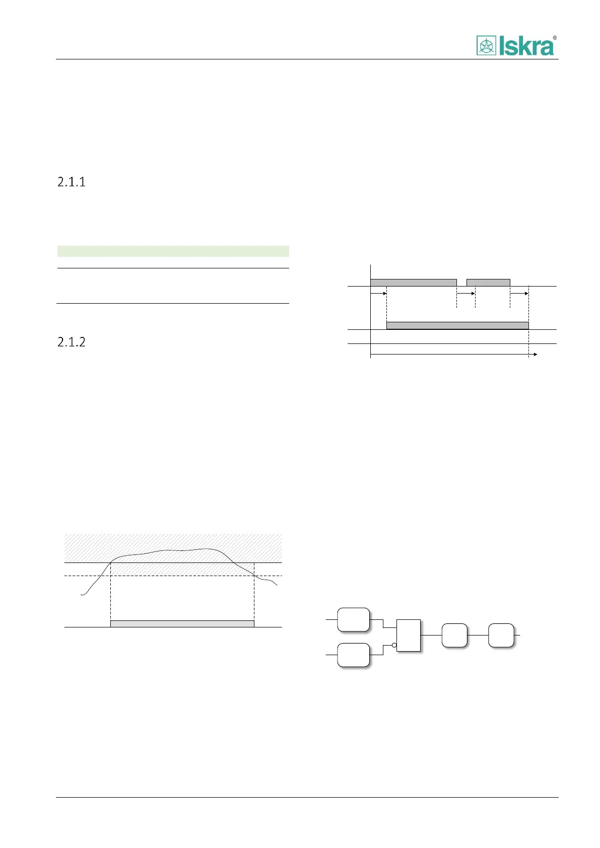
Operational scenario is illustrated on Figure 2.2. Drop-
out delay prevents the timer of protection function to
reset in case the fault falls below the pickup value for a
short period of time. It is usually used when very long
time characteristics are used. In case the protection
trips, drop out delay is not accounted for and other
means of delaying trip signal are used.
Pickup signal
Fault detection
Trip signal
Pickup
delay
Trip delay
Drop-out
delay
Drop-out
delay
Figure 2.2: Pickup signal and Trip signal when fault duration is
shorter than trip delay.
2.1.2.1 Pickup logic
The pickup signal indicates that monitored value
exceeded the set value and indicates that a fault
occurred (Figure 2.2). The pickup delay is intended for
fault signalling stabilization to prevent the short-lived
disturbances in the measuring part of the system from
being reported as faults (Figure 2.4).
The pickup is set (Figure 2.3):
When a fault is detected and
Pickup delay confirmation time runs out and
There is no blocking
Fault
detection
Pickup
Blocking
Pickup
Delay
Pickup
&
Figure 2.3: Pickup set logic.