Functionality
20 USER MANUAL FPC 200 - 3/2017
2.2 Current based protections
Overcurrent protection - ANSI code 50/51
Overcurrent protection is one of the basic functions of FPC 200 numerical relays. It protects the feeder or other elements
of the power system from overcurrent when fault occurs. It comprises of various time-delayed characteristics. Protective
function includes Inrush restraint [2.2.5] and Cold load pickup (CLP) protection.
2.2.1.1 Functionality
Overcurrent protection is used as non-directional time
delayed overcurrent and short-circuit protection. It picks
up when current in one, two or three phases exceeds
the set threshold. The function can be enabled or
disabled through corresponding menu. The trip time
characteristics can be selected to be Instantaneous,
definite time (DT) or inverse definite minimum time
(IDMT). When instantaneous operation mode is selected
the trip signal is stated as the DT characteristic. The
settings of this function are applied to each of the three
phases to produce pickup and trip signals per each
phase.
Several overcurrent protection instances with different
settings can run independently at the same time.
The selection of pickup value, pickup delay as well as
drop-out ratio and drop-out delay helps the user to fine
tune the protection according to the project
specifications.
50/51 Over current
Mode:
Enable:
IDMT coeficient:
0,02
ON
Pickup value: 1,2xIn
A
Trip delay: 0,4s
Ext. inverse
1A 1B 2A 2B 3A 3B 4A
Figure 2.16: Overcurrent protection setting.
2.2.1.2 Measurements
The value of each phase current is acquired through
separate input current transformer. The measured
phase currents are compared with the set pickup value.
2.2.1.3 Delays
Function includes following delays explained in Chapter
2.1:
Pickup delay
Trip delay
Drop-out delay
2.2.1.4 Cold load pickup
A temporary increased starting current can appear
when energizing feeders with loads that had a long zero
voltage period (e.g. air-conditioning systems, heating
installations, motors...). Its value can be up to several
times higher than the nominal current. To avoid
unwanted protection operation the pickup limit has to
be raised temporarily. The function is set with
parameter Enable. It triggers through the activation of
corresponding digital input or when current raises
above
5 % of I
n_obj
in at least one phase after certain amount
of time has passed.
The dynamic pickup value changeover is common to all
overcurrent elements. With inverse characteristics, the
CLP influences only the fault detection limit, whereas
the time calculation of the selected inverse
characteristic is not affected.
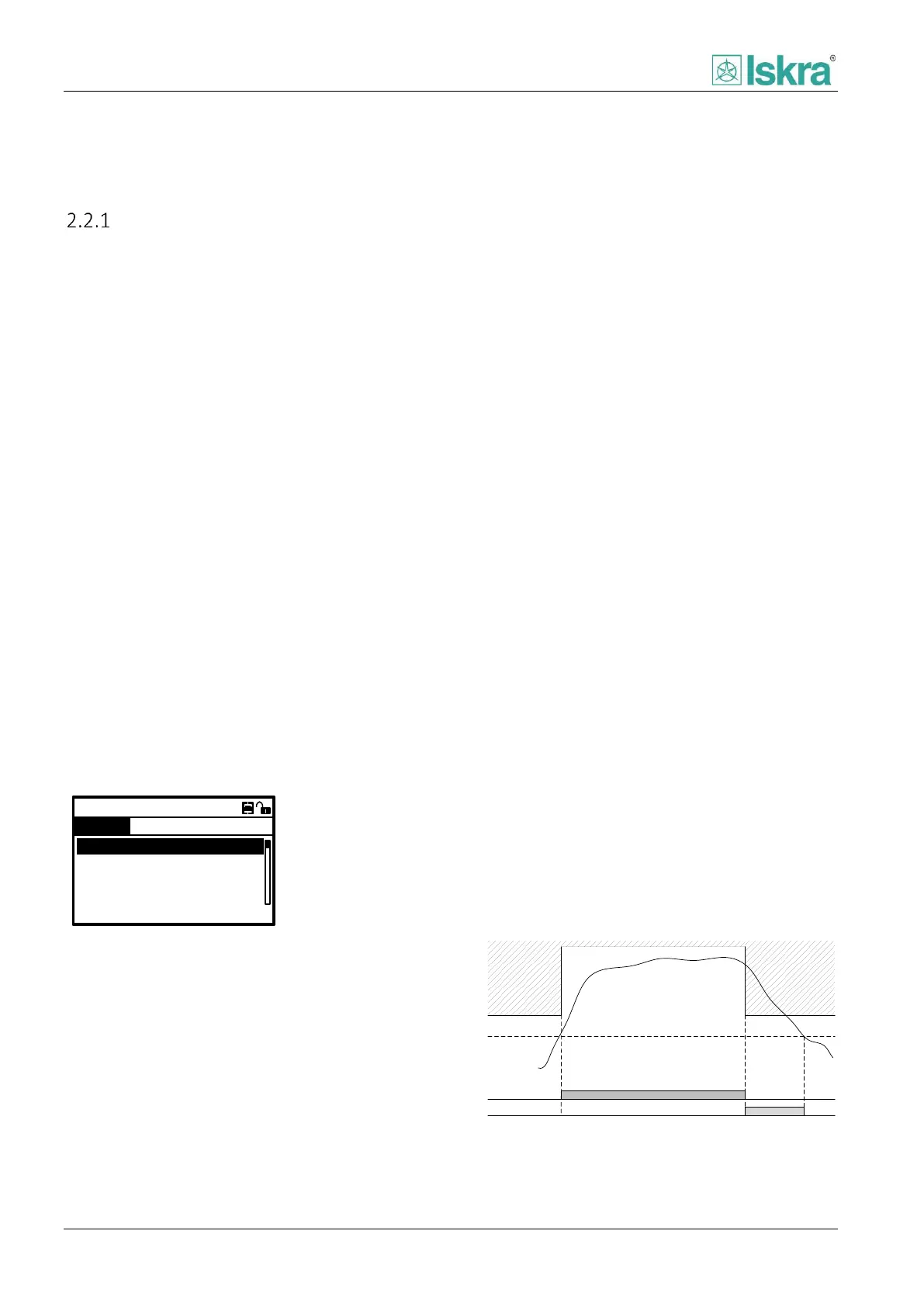
Pickup value
Drop-out value
CLP activated
Monitored value
Fault area
Fault detection
Figure 2.17: Operation with CLP activated for a shorter than
fault time duration.