Mounting and commissioning
160 USER MANUAL FPC 200 - 3/2017
5.6 External module
External module is mounted to a rail size 35 mm x 7,5 mm or 35 mm x 15 mm according to EN 50022. External module
can be connected to device using the dedicated cable with RJ45 connector.
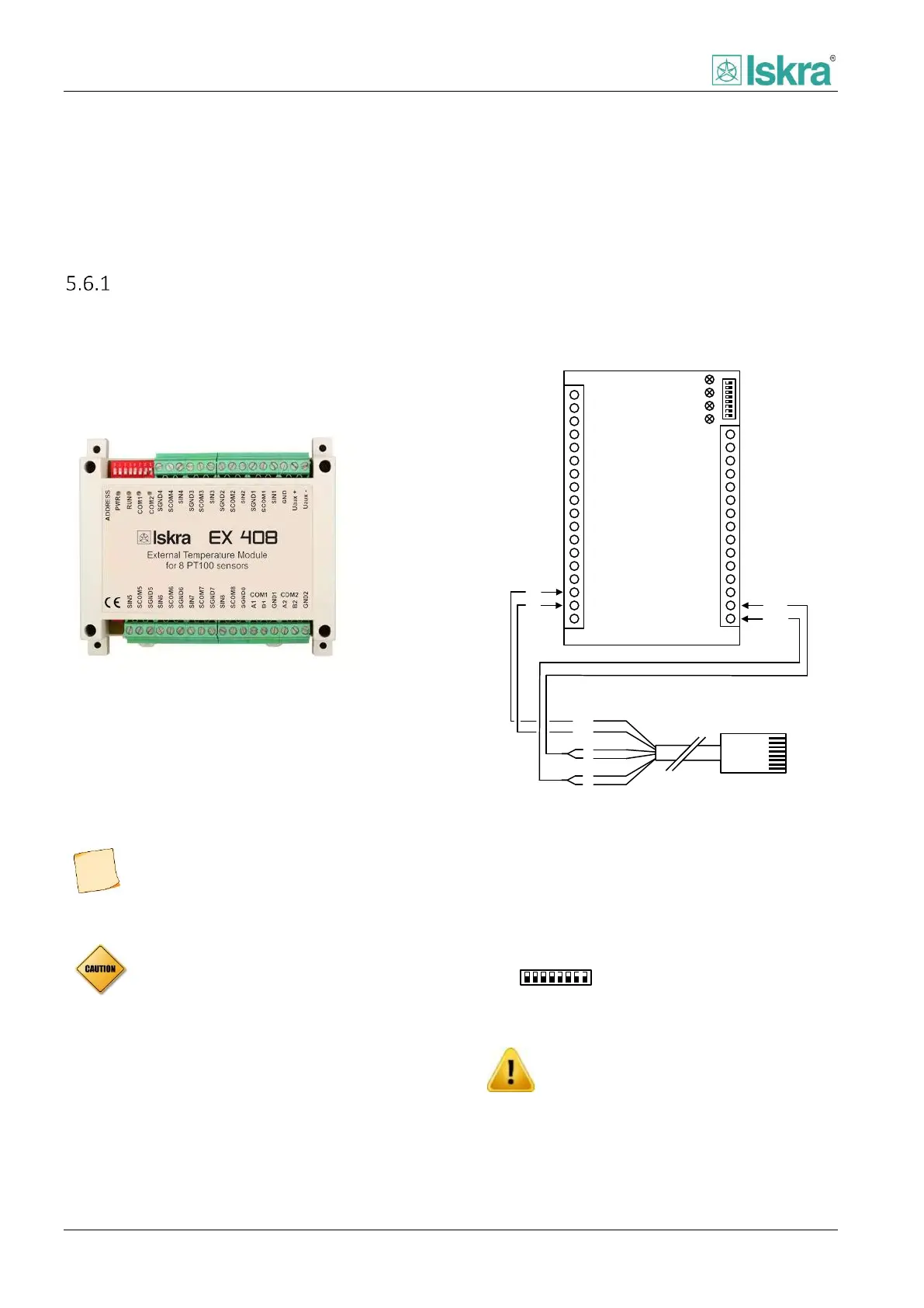
EX 408 Temperature module
The connection itself also serves as the power supply
and communication between the device and external
module. The proper RJ45 connector placement on the
device can be found in connection scheme, section
[5.5.2] on Figure 5.7 and Figure 5.8.
Figure 5.10 External module top view.
5.6.1.1 External module operation
External module uses 2 or 3 – wire connection type with
RTD probe. Device interprets the data acquired with
module and displays them in appropriate display screen
as can be seen on Figure 2.52.
External module does not need its
individual power supply as it is powered
from the RJ45 communication port
It is necessary that the device is equipped
with any type of communication card in
order to successfully install external
module.
5.6.1.2 External module diagram
The following diagram represents external module and
its pin configuration
Uaux +
Uaux -
GND
SCOM1
SGND1
SIN1
SCOM2
SGND2
SIN2
SCOM3
SGND3
SIN3
SCOM4
SGND4
SIN4
COM2
COM1
RUN
PWR
SCOM8
SGND8
SIN8
SCOM7
SGND7
SIN7
SCOM6
SGND6
SIN6
SCOM5
SGND5
SIN5
GND1
B1
A1
GND2
B2
A2
A
U+
U-
4,5
7,8
B
1
2
EX 408
A
U+
U-
1
2
3
4
5
6
7
8
RJ45
1
2
4
5
7
8
B
To port F
EX 408
3
Not used
6
Not used
Figure 5.11 EXT 408 Module connection diagram including
RJ45 connection cable.
5.6.1.2.1 Dip switch configuration
There are 8 dip-switches mounted on external module.
Their configuration must be placed on ON for all Dip-
switches.
Figure 5.12 Dip-switch configuration for EXT 408.
Dip switch configuration shall not be
changed as it may result in improper
module operation and possible property
damage.