Functionality
USER MANUAL FPC 200 - 3/2017 79
Symmetrical components
By using three symmetrical systems any three-phase
non-symmetrical system can be presented. These
systems are named positive negative and zero sequence
systems:
Positive sequence indicates rotating magnetic
field in native direction. In fully symmetrical
three phase system only positive sequence is
present while negative and zero sequence
have zero value.
Negative sequence value indicates presence
of rotating magnetic field in opposite direction
than native direction of three phase system.
Zero sequence is present if three-phase system
is not balanced
three times zero sequence
three times zero sequence
Table 79 Symmetrical components values.
Temperature
Measurement is performed by using appropriate
external module [5.6.1]. Specific algorithms are used to
interpret measurement of probes resistance. RTDs are
using 3-wire connection type to temperature sensors.
The measured temperatures are updated each second.
Following RTD type is supported:
Table 80 Type of supported RTD.
2.9.7.1 Minimum and maximum measured
values
Each probe has a lower and upper limit, indicating
malfunction of probe if the measured temperature
exceeds this limits. If any limit is exceeded a dedicated
sign is presented on HMI. In addition average, maximal,
and minimal temperature can be accessed for each
individual probe.
Table 81 Maximum and minimum limits of temperature
measurement.
Detection of open probe
contacts
Detection of short circuit
probe contacts
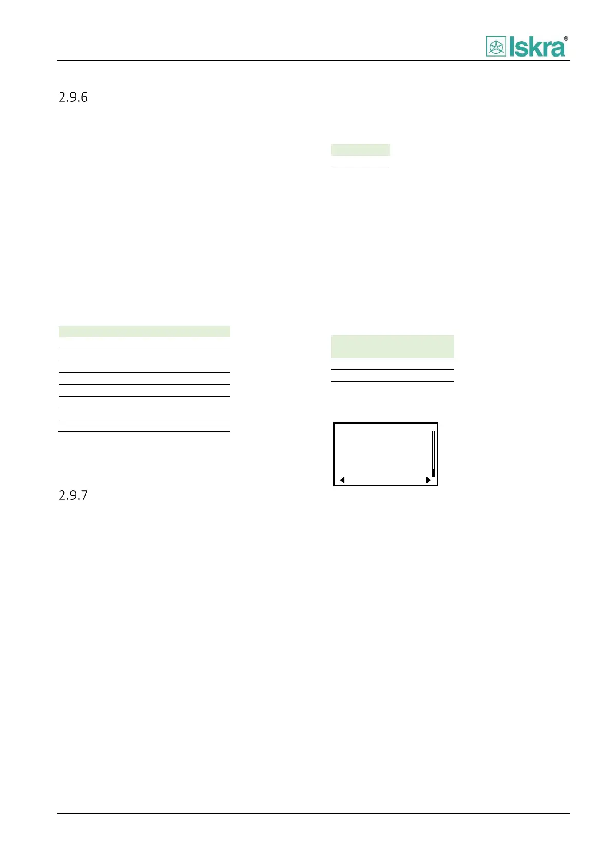
1: 24°C
2: 24°C
3: 24°C
4: 24°C
5: 24°C
6: 24°C
7:N/A°C
8:---°C
Current temp. 1-8
7:N/A°C
8:---°C
Figure 2.52 Temperature measurement as presented on HMI. If
any temperature limit is exceeded a dedicated sign is
presented.