Communication
82 USER MANUAL FPC 200 - 3/2017
3 Communication
FPC 200 can be connected to supervision communication network based on following communication protocols:
Modbus RTU
IEC60870-5-103
3.1 Modbus RTU
General description
Modbus communication protocol uses request-reply
logic to obtain information from dedicated devices. The
device that executes request is always a master and
device that listens to request is always a slave. Modbus
protocol allows several slave devices to be connected to
a single master device. Individual devices are addressed
by a specific code unique to each slave device
connected to communication network. FPC 200 is
always a slave station and it allows to be connected to
any other device with Modbus master communication
channel.
Modbus PDU (protocol data unit)
Every Modbus character frame send or received consists
two fields which assign function code being used and
data being transferred. The total number of data bits to
be transferred in one package is dependent of the
transfer function to be used. If there was no error
during transmission of data function codes in request
and reply are identical. There are two types of data that
can be transmitted, bits (also called Coils) and 16 bit
words (also called Registers). Words used to transfer
data are always represented in big-endian format.
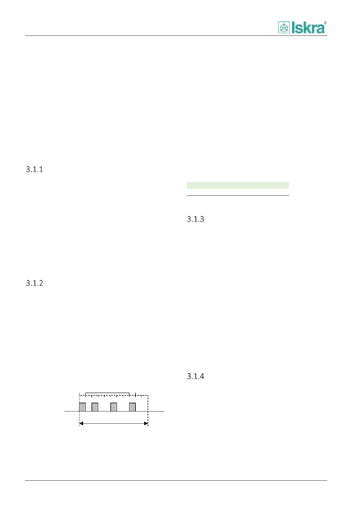
Bit information
Character frame
Start
bit
Data
bits
Parity
bit
Stop
bits
IdleIdle
Figure 54 Modbus RTU character frame
Table 84 Modbus PDU format.
Modbus function supported
Modbus protocol uses standard set of functions.
Functions are divided by the ability to read or write one
or multiple data bits.
3.1.3.1 Read functions:
Function 2: reading of n input bits
Function 3: reading of n output or internal bits
Function 4: reading of n input words
3.1.3.2 Write functions:
Function 5: writing of 1 bit
Function 6: writing of 1 word
Function 16: writing of n words
Time synchronization
Time synchronization zone is dedicated to set exact time
to the device. To write time massage function 16
containing 4 words should be used. Reading device time
massages can be done separately word by word, or by
using a multiple words function 3 can be used to access
whole timestamp instead. It is possible that internal
clock could drift over time. To ensure that device
internal time is set correctly, time synchronization
should be carried out over regular intervals of 10 to 60