Functionality
78 USER MANUAL FPC 200 - 3/2017
2.9 Measurements
Measurement values can be accessed by reading it via communication [3.1.7.3] or by accessing them using
dedicated PC based software [4.3.2.4] or by using local HMI [4.2.4.2].
Presented measured values
Device is able to measure currents or voltages.
According to model measurement card consist of four
analog measured values. Device measures and
calculates presented values of currents or voltages and
displays them. Measurements are presented in:
RMS,
average RMS in user defined interval cycle
time,
peak of average RMS,
RMS in bar maximum 150 % of
,
separate harmonics up to 9
th
harmonic,
harmonics presented in percent of RMS value
in bars separately,
phase unbalance,
frequency.
A
A
A
A
128.4
135.6
132.4
5.2
IL2RMS=
IL3RMS=
IeRMS=
IL1RMS=
Figure 2.50Example of current measurement screen as seen on
HMI.
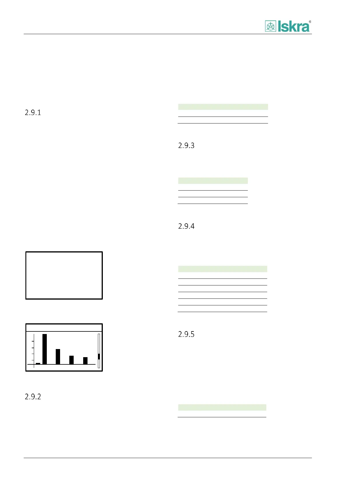
Harmonics
2 3 4 5 6 7 8 9
%
3
1
2
4
THD=6%
IL1=235A
f=50Hz
Figure 2.51 Example of harmonics overview as seen on HMI.
Nominal values
Nominal values U
n
and I
n
are calculated based on user
defined settings in analog inputs section [4.2.4.5.4].
Table 75 Nominal values of the device.
Current measurement
The value of each of phase currents and earth current is
acquired through dedicated input current transformer.
Table 76 Measured current values.
Voltage measurement
The value of each of phase to phase voltages is
calculated through measured phase voltages of
measurement voltage transformers.
Table 77 Measured voltages values.
Frequency measurement
Frequency is determined based on healthy analog
acquisition line measurement with priority of phase
voltage measurements first, than phase current
measurements. In addition the healthy line is
considered as a line which value is nearest to U
n
or I
n
.
Device frequency determines FFT window length to be
used in exact device measurement of analog values.
Table 78 Frequency value.