Settings
USER MANUAL FPC 200 - 3/2017 123
Lockout relay
Enabling of Lockout relay functionality is done under
corresponding header of CB control menu. Detailed
description can be found in section [2.6.1.12]
Counters
Appropriate counters are presented at the end of CB
control menu, list can be found in section [2.6.1.15].
4.2.4.5.3 Communication
Communication submenu consists of all communication
settings. Menu is adjusted for specific ordered
communication protocol.
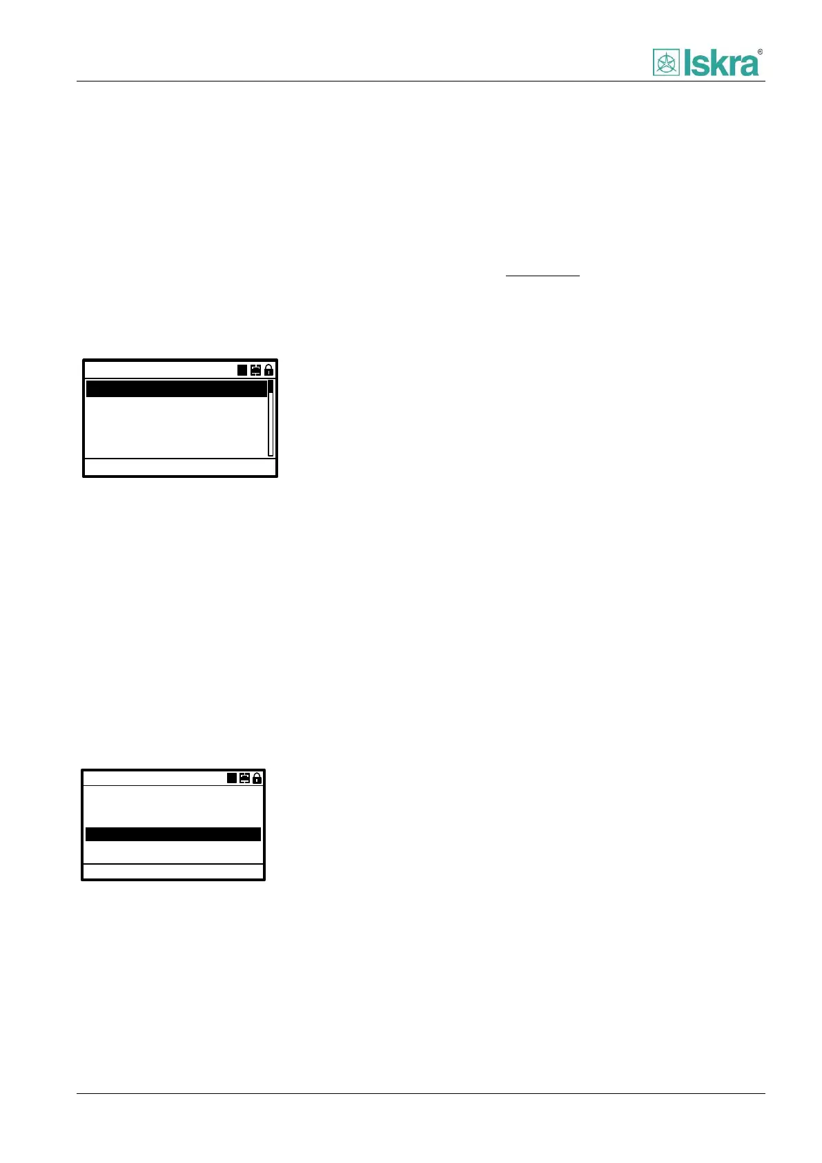
Modbus RTU
Protocol:
115200
Change settings: ACC
1
Device address:
Baud rate:
Communication
AA
Stop bits:
1
None
Parity:
Figure 4.18 Example of communication menu.
Protocol
Protocol presents device communication software
installed. All parameters below are referred to specific
communication protocol. More advanced information
can be found in Chapter 3.
4.2.4.5.4 Analog inputs
Analog inputs are used for fundamental measurement
of currents and voltages used in protecting switchgear.
Analog inputs use currents and voltages from current
and voltage instrument transformers installed in
switchgear. The following parameters of submenu may
differ for different device types.
Analog inputs
IL Nominal:
300A
ACC
CT Primary:
IeCT Primary:
300A
50A
CT Secundary: 1A
Change settings:
A
IeCT Secondary:
1A
Figure 4.19 Example of analog inputs menu.
Rated nominal current of the object [IL Nominal]
Rated nominal current of the object I
n_obj
(outgoing
feeder, motor, etc.). The value is later used on
calculation and display of specified value in p.u. units.
The parameter defines 1 p.u. of protected element.
Example:
Calculation of motor phase currents based on nominal
primary current of the motor I
n_obj
:
Device measure current I
S
= 0.7 A
That would mean that motor phase currents I
n_obj
are
currently at 80 % of its nominal value.
CT Primary
Rated primary current of installed current transformer
I
pri
.
CT Secondary
Parameter for rated secondary current of installed
current transformer I
n
. This parameter is multiple choice
option between 1 A and 5 A.
IeCT Primary
Rated primary current of installed earth current
transformer I
e_pri
.
IeCT Secondary
Parameter for rated secondary current of installed earth
current transformer I
e_n
. This parameter is multiple
choice option between 1 A and 5 A.
VT primary
Rated primary phase to phase voltage of installed
voltage transformer U
pri
.
VT secondary
Rated secondary phase to phase voltage of installed
voltage transformer U
n
.
UeVT primary
Rated primary phase voltage of installed earth voltage
transformer U
e_pri
.
UeVT secondary
Rated secondary phase voltage of installed earth voltage
transformer U
e_n
.
4.2.4.5.5 Analog outputs DC
Analog output presents information about fundamental
measurement and calculations of the device in form of
output current. The output current ranges maximally
from 0 mA to 20 mA. Output current peak to peak value