Settings
124 USER MANUAL FPC 200 - 3/2017
is user defined. On the device it is possible to use 3
separate analog outputs.
Analog output 1
Source:
IL1
ACC
Output range:
High value:
0-20mA
300A
Low value: 0A
Change settings:
A
Figure 4.20 Example of analog outputs menu.
Source
Parameter defines fundamental measurement or
calculation which magnitude is used as analog output
magnitude.
Output range
Analog output can be set inside following ranges:
0-10 mA
4-10 mA
0-20 mA
4-20 mA
Low value
Defines the point of fundamental measurement or
calculation at which output current is minimal.
High value
High value defines the point of fundamental
measurement or calculation at which output current is
at its maximum.
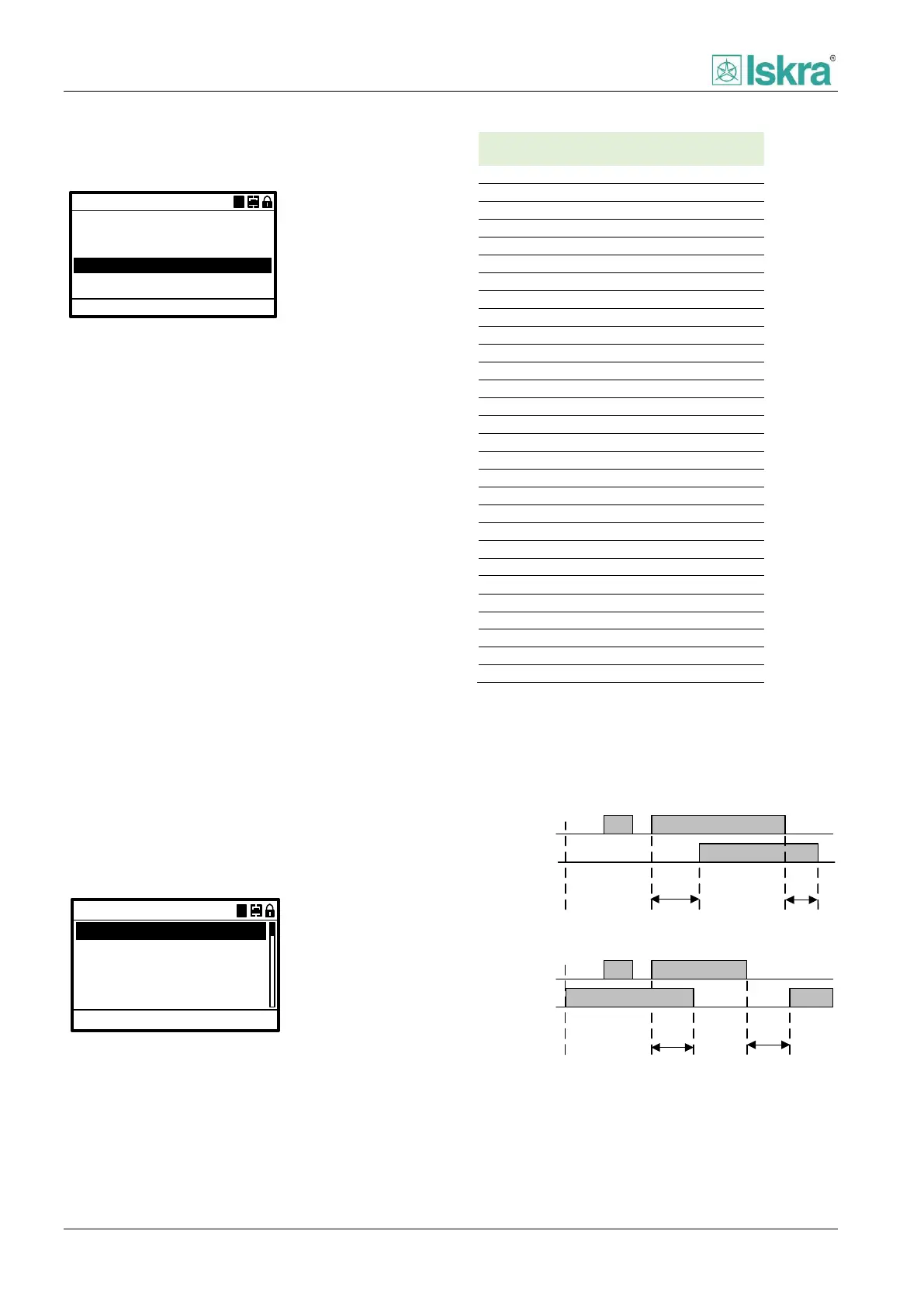
4.2.4.5.6 Digital inputs
For control purposes there are 0-10 total available
digital inputs. Function, control logic positive or negative
and delay for each DI can be configured according to
application.
0ms
Change settings: ACC
Input:
Active-HI
None
Logic:
ON delay:
OFF delay:
0ms
Digital input 1
AA
Show event:
No
Figure 4.21 Example of parameter settings of single digital
input menu.
Input
Defines specific input signal to be matched to
predefined internal signal.
Logic
Digital input logic defines state for specific input to be
active.
DI1
DI1 active
ON
delay
Active-LO logic
OFF
delay
DI1
DI1 active
ON
delay
Active-HI logic
OFF
delay
Figure 4.22 Active HI and LO logic of digital input.
ON delay
Signal duration needed for input to change state to
active.