Settings
USER MANUAL FPC 200 - 3/2017 125
OFF delay
Signal duration needed for input to change state to
inactive.
Show event
Display change of specific input in events respectively.
4.2.4.5.7 Digital outputs
For means of communication, operation and display
functions, software of relay operates using three types
of internal signals:
- Trip
- Pickup
- Command/control
Control matrix can be used to assign internal signals of
individual elements (etc. individual protections) to
interact with output relays or LED indicators. The Figure
4.23 represents selection of Digital outputs menu.
Digital outputs
Relay settings
Relay mapping
Assign relays
Assign LEDs
Figure 4.23 Section of assignment menu.
Relay settings
Relay basic options can be found in Relay settings
submenu. According to general purpose for each
individual output relay a basic options can be set.
Relay settings
Relay 2
Relay 1
Relay 3
Relay 5
Relay 4
Relay 6
A
T
Current relay
status
Trip relay
ACC
Relay 1
Logic:
Active-ON
ACC
Pulse width:
0ms
ON delay: 0ms
Change settings:
A
R
Ready relay
Figure 4.24 Settings of individual output relay
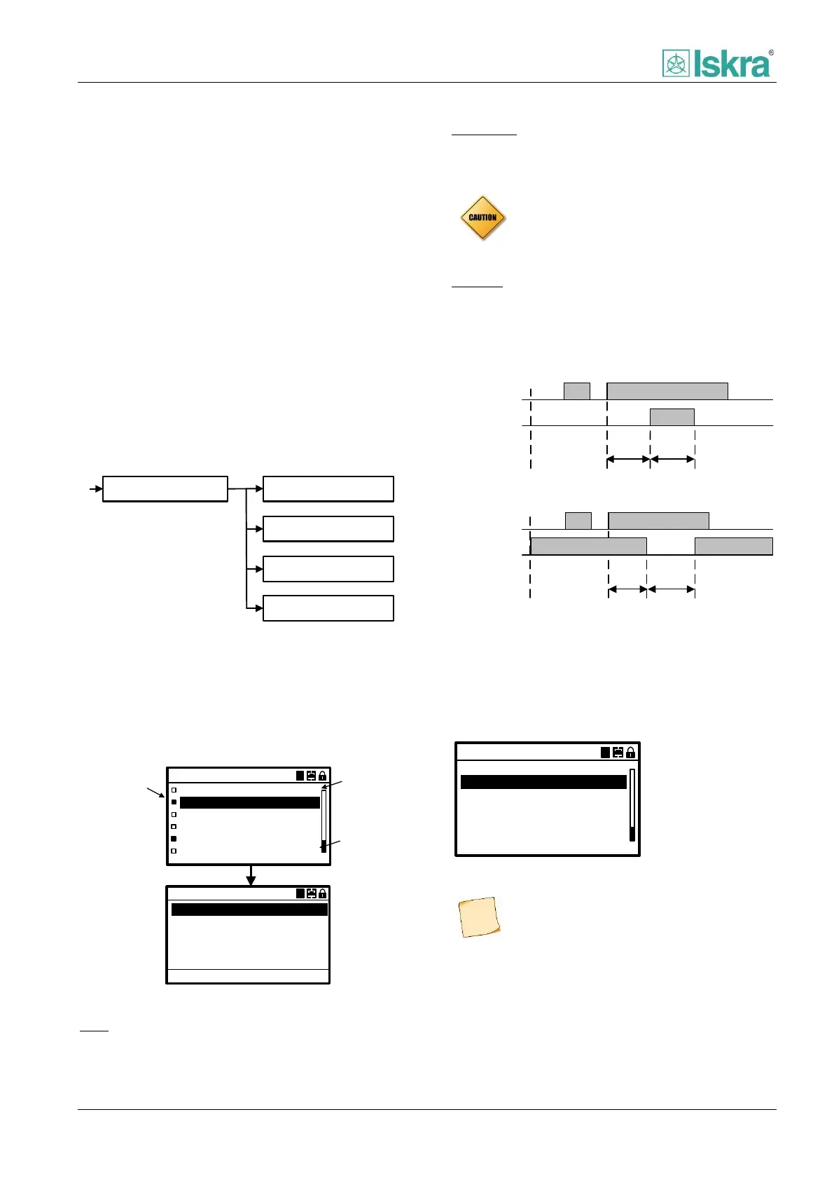
Logic
Digital output logic defines state of specific output relay
at non-active position.
Pulse width
States time which defines output relay to be active after
certain signal become apparent.
Only for trip relay a trip signal has priority
over pulse width setting.
ON delay
Time delay after which output relay becomes active
Active-OFF logic
Signal active
ON
delay
Relay 2
(Pulse mode)
Pulse
width
Relay 2
(Pulse mode)
Signal active
ON
delay
Active-ON logic
Pulse
width
Figure 4.25 Output relay logic.
Relay mapping
Trip relay, Close relay 1, Close relay 2 and Ready relay
are mapped in Relay mapping menu. Also open
commands are executed on trip relay.
Relay mapping
Close relay 1:
Trip relay:
Close relay 2:
A
Ready relay:
Do6
Do1
Do3
None
Figure 4.26 Assigning different types to specific output relays.
Ready relay can be mapped only to DO6. In
case if it is mapped to ready relay the
setting logic: Active-OFF is not taken into
account.