Settings
122 USER MANUAL FPC 200 - 3/2017
4.2.4.5 Device setting
Options to set and control device are located in this section of tree menu.
4.2.4.5.1 General settings
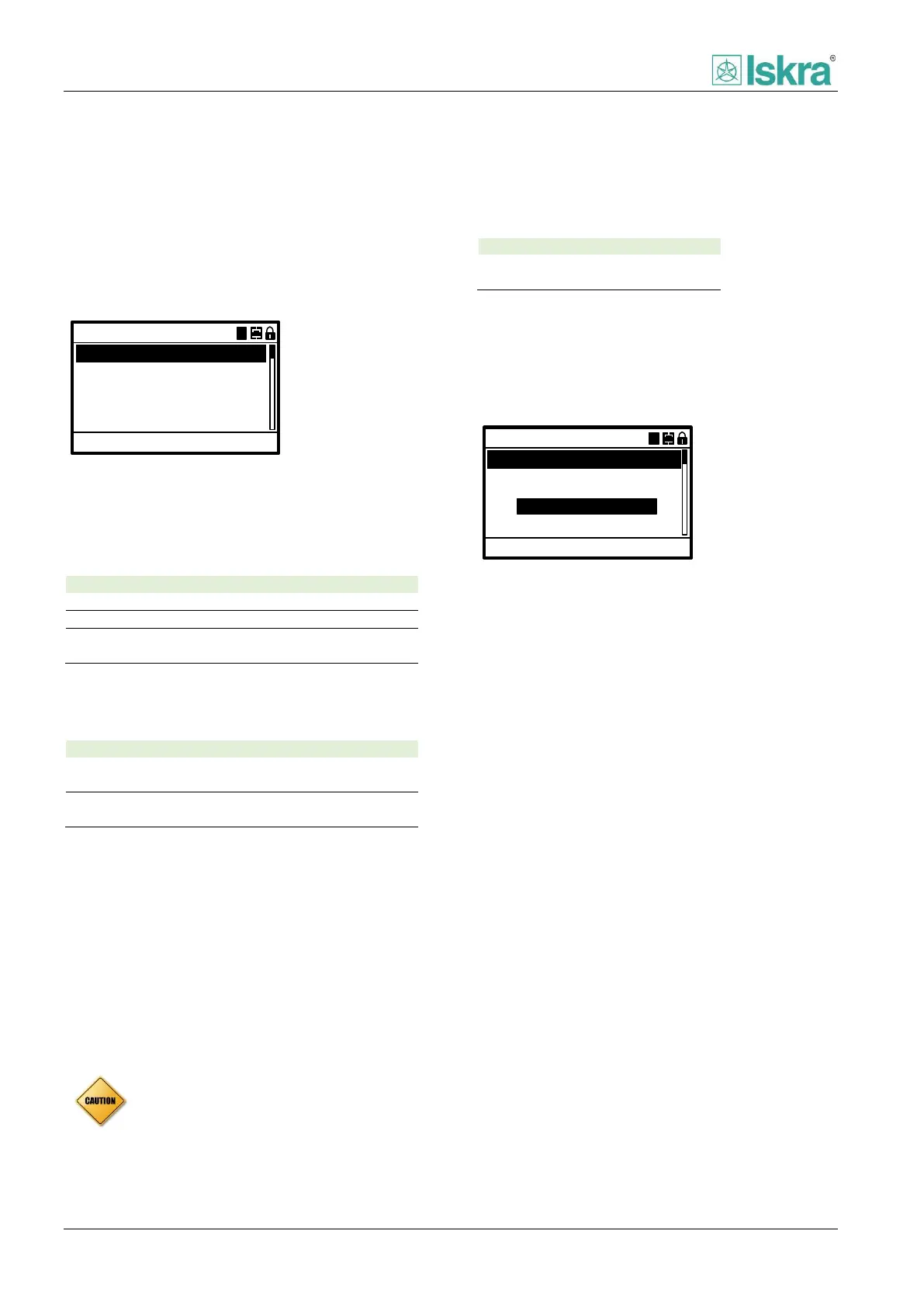
General settings define basic settings for device to be
operational.
13:27:12
Change settings: ACC
Active Group:
50Hz
A
Frequency:
Time:
Date:
05.02.2016
General settings
AA
Cycle time:
10min
Figure 4.16 Example of general settings menu.
Active group
Active group defines the running group of protection
settings.
First group of protection settings
Second group of protection settings
Group selection by digital input or
communication
Frequency
Frequency parameter defines nominal frequency used in
national power system.
Use this if national frequency of power
system is 50 Hz
Use this if national frequency of power
system is 60 Hz
Time
This parameter is used to set and show current device
time.
Date
This parameter is used to set and show current device
date.
Cycle time
Cycle time defines refresh rate of average values used in
measurements.
4.2.4.5.2 CB control
This section defines how the device will operate with CB
all the details about operation can be found in section
2.6.1.
0.2s
Cmd. timeout:
9ms
Change settings: ACC
100ms
Oper. time:
DO close time:
CB control
AA
Source:
Local
COMMAND OBJECTS
Figure 4.17 Example of circuit breaker control menu.
Command timeout [Cmd. timeout]
Time of command execution can be set in this section.
Detailed description can be found in section [2.6.1.3.1]
Operation time [Oper. time]
Time defining switchgear primary contact separation.
Detailed description can be found in section [2.6.1.3.2]
Remote enabled
Parameter that enables remote commands in addition
with local HMI or commands over DI. Detailed
description can be found in command objects section
[2.6.1.4]
Interlocking
Table lists abbreviation for interlocking is presented in
Table 54. Detailed description of interlocking start at
section [2.6.1.3]
Circuit breaker failure [CBFP]
Circuit breaker failure function can be enabled and set
under CBFP header in CB control menu. Detailed
description can be found in section [2.6.1.10]
Ready
Ready value of switchgear element can be defined in
this section. Detailed description can be found in section
[2.6.1.11]
Ready value does not count as interlock for
executing commands.