Functionality
USER MANUAL FPC 200 - 3/2017 61
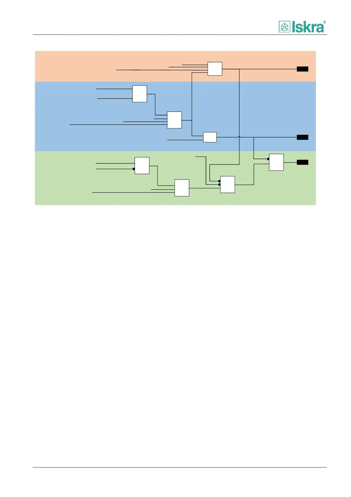
Interlocking
Trip circuit supervision (74TCS)
SF6
Overcurrent (50/51)
Earth fault overcurrent (50/51|N/G)
External protection
Auto-reclosure (79) Open command
Open command
by local display
Remote open command
Remote close command
Block remote control
Breaker closed
Auto-reclosure (79) Close command
Close command by local display
Block
Open
Close
≤1
≤1
&
≤1
&
≤1
&
≤1
Figure 2.36: Blocking diagram.
2.6.1.3 Control settings
2.6.1.3.1 Command timeout
Time used for a device to wait for switchgear element to
change state. If this time is exceeded and no return
information was given, an error Command failed popup
window will be displayed on HMI in addition an
information can be accessed using the available
communication protocol.
2.6.1.3.2 Operation time
Time measured from moment when device relay
contacts initiate switchgear open command till moment
when switchgear element primary contacts open. This
information is vital calculation of cumulative breaking
current of primary contacts [2.6.1.7]. The information is
usually available in circuit breaker technical data.
2.6.1.4 Command objects
Command objects defines the source of which the
switchgear element commands are executed.
Commands via HMI and DI are always allowed and
commands via communication can be allowed in
addition. In case that Remote enabled signal is assigned
to DI, this setting is not displayed on HMI.
2.6.1.5 Interlocking system
Interlocking system serves as a switch allowing remote
or local commands to be issued. Local commands are
always allowed while remote command can be allowed
by using parameter via HMI, MiQen software, Modbus
table and DI.
2.6.1.6 Max trip open (MTO)
Max trip open is a cumulative counter of CB trips. Alarm
and Block signal can be set after a certain number of trip
signals dedicated to open CB has passed. If number
present exceeds a Block set limit a circuit breaker MTO
interlock will engage.
2.6.1.7 Cumulative breaking current I
2
t
Function indicates the cumulative breaking current in
square kilo amperes. Total sum number information of
each phase is provided in appropriate diagnostic section
[4.2.4.1.3]. Alarm and block signal can be set for certain
amount of cumulative breaking current. If number
present exceeds a Block set limit a circuit breaker I
2
t
interlock will engage.
Current calculation is performed every time a command
open is executed or trip signal dedicated to open a CB is