Mounting and commissioning
USER MANUAL FPC 200 - 3/2017 161
5.6.1.3 Connecting the external modules
connection cable.
The following diagram explains connection of external
module with the device. The RJ45 connector is
connected to port for external modules [5.5.2] on
communication card of the device.
Table 113 Connection cable pin configuration on EX408 side.
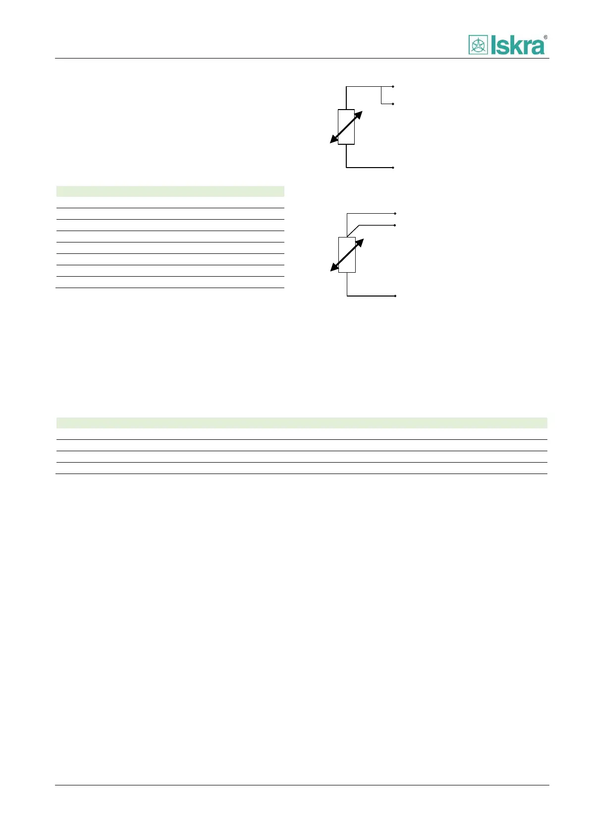
5.6.1.4 Probe connection diagram
The module is designed to be connected with 3-Wire or
2-Wire probes.
SINx (White)
SCOMx (Red)
SGNDx (Red)
Figure 5.13 2-Wire connection diagram.
SINx (White)
SCOMx (Red)
SGNDx (Red)
Figure 5.14 3-Wire connection diagram.
5.6.1.5 Physical characteristics
IP50, IP20 for connection terminals
Table 114 External module physical characteristics.