Electrical installation
Page 100
8.10 Connector: CAN bus [X4]
8.10.1 Configuration on the device [X4]
D-SUB connector, 9-pin type, male
8.10.2 Mating connector [X4]
D-SUB connector, 9-pin type, female
Housing for a 9-pin D-SUB connector with locking screws of type 4/40 UNC
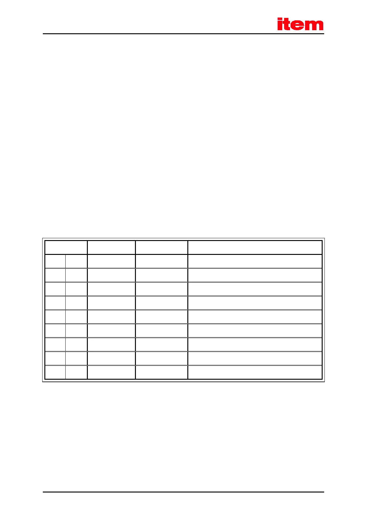
8.10.3 Pin assignment [X4]
Table 43: Pin assignment CAN bus [X4]
1 Not used
6 GND 0 V CAN-GND, electrically coupled to GND in the controller
2 CANL
*)
CAN low signal line
7 CANH
*)
CAN high signal line
3 GND 0 V See pin no. 6
8 Not used
4 Not used
9 Not used
5 Shield PE Connector for the cable shield
*)
An external terminating resistor of 120 Ω is required on both ends of the bus. If the bus ends are not formed by item Servo
Positioning Controller C 3-Series with integrated terminating resistors, we recommend using metal film resistors with a 1%
tolerance of type 0207, e.g. made by BCC, part no.: 232215621201.

 Loading...