Electrical installation
Page 96
8.8 Connector: incremental encoder input [X10]
8.8.1 Configuration on the device [X10]
D-SUB connector, 9-pin type, female
8.8.2 Mating connector [X10]
D-SUB connector, 9-pin type, male
Housing for a 9-pin D-SUB connector with locking screws of type 4/40 UNC
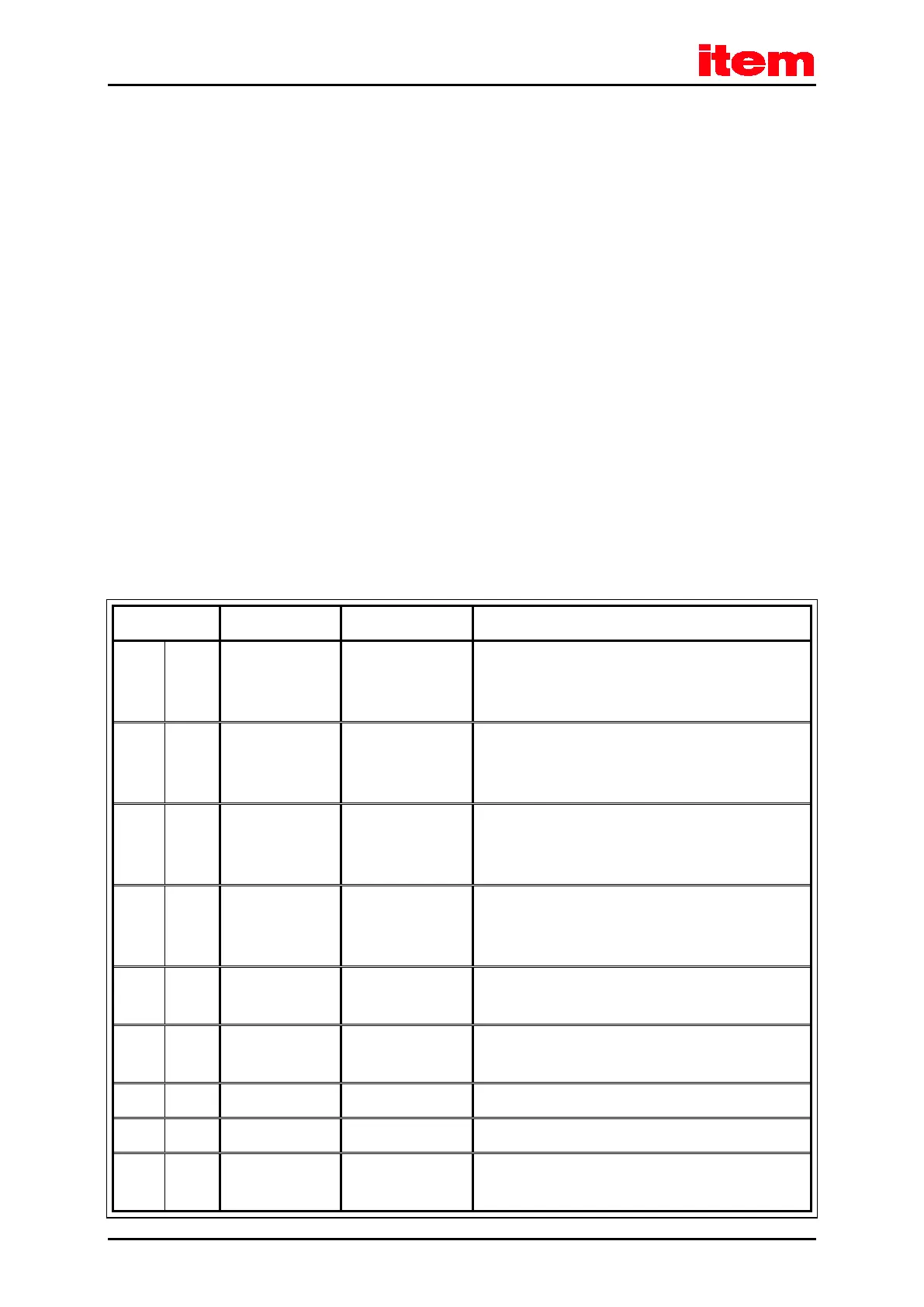
8.8.3 Pin assignment [X10]
Table 41: Pin assignment [X10]: incremental encoder input
1 A / CLK 5 V / R
I
≈ 120 Ω Incremental encoder signal A /
stepper motor signal CLK
pos. polarity as per RS422
6 A# / CLK# 5 V / R
I
≈ 120 Ω Incremental encoder signal A# /
stepper motor signal CLK
neg. polarity as per RS422
2 B / DIR 5 V / R
I
≈ 120 Ω Incremental encoder signal B /
stepper motor signal DIR
pos. polarity as per RS422
7 B# / DIR# 5 V / R
I
≈ 120 Ω Incremental encoder signal B# /
stepper motor signal DIR
neg. polarity as per RS422
3 N 5 V / R
I
≈ 120 Ω Incremental encoder index pulse N
pos. polarity as per RS422
8 N# 5 V / R
I
≈ 120 Ω Incremental encoder index pulse N#
neg. polarity as per RS422
4 GND Reference GND for the encoder
9 GND Shield for the connecting cable
5 VCC + 5 V / ± 5%
100 mA
Auxiliary supply (short-circuit-proof), maximum load
100 mA!

 Loading...