Technical data
Page 37
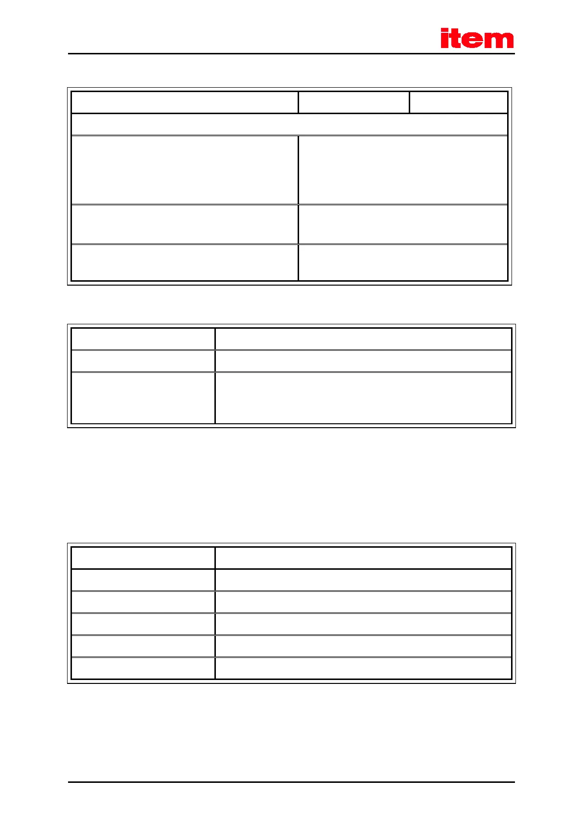
Table 7: Technical data: cable specifications
Maximum motor cable length for interference emission as per EN 61800-3
Category C2
Installation in a switch cabinet (see
chapter 8.14 Notes
concerning the safe and EMC-compliant
installation
) to be
performed by a specialist
l ≤ 50 m
Category C3
(industrial environment)
l ≤ 50 m
Cable capacity of one phase against shield or between two
lines
C‘ ≤ 200 pF/m
Table 8: Technical data: motor temperature monitoring system
Motor temperature monitoring system
Digital sensor N.C. contact: R
cold
< 500 Ω R
hot
> 100 kΩ
Analogue sensor Silicon temperature sensor, e.g. KTY81, 82 or similar
R
25
≈ 2000 Ω
R
100
≈ 3400 Ω
4.2 Control elements and display elements
On its front panel, the item Servo Positioning Controller C 3-Series has three LEDs and one seven-segment display to indicate
the operating status.
Table 9: Display elements and RESET button
Seven-segment display Indication of the operating mode and of an error code in the event of malfunctions
LED 1 (two-colour LED, green/red) Operational readiness or errors
LED 2 (green) Controller enable signal
LED 3 (yellow) CAN bus status indication
RESET button Hardware reset for the processor
 Loading...
