Electrical installation
Page 99
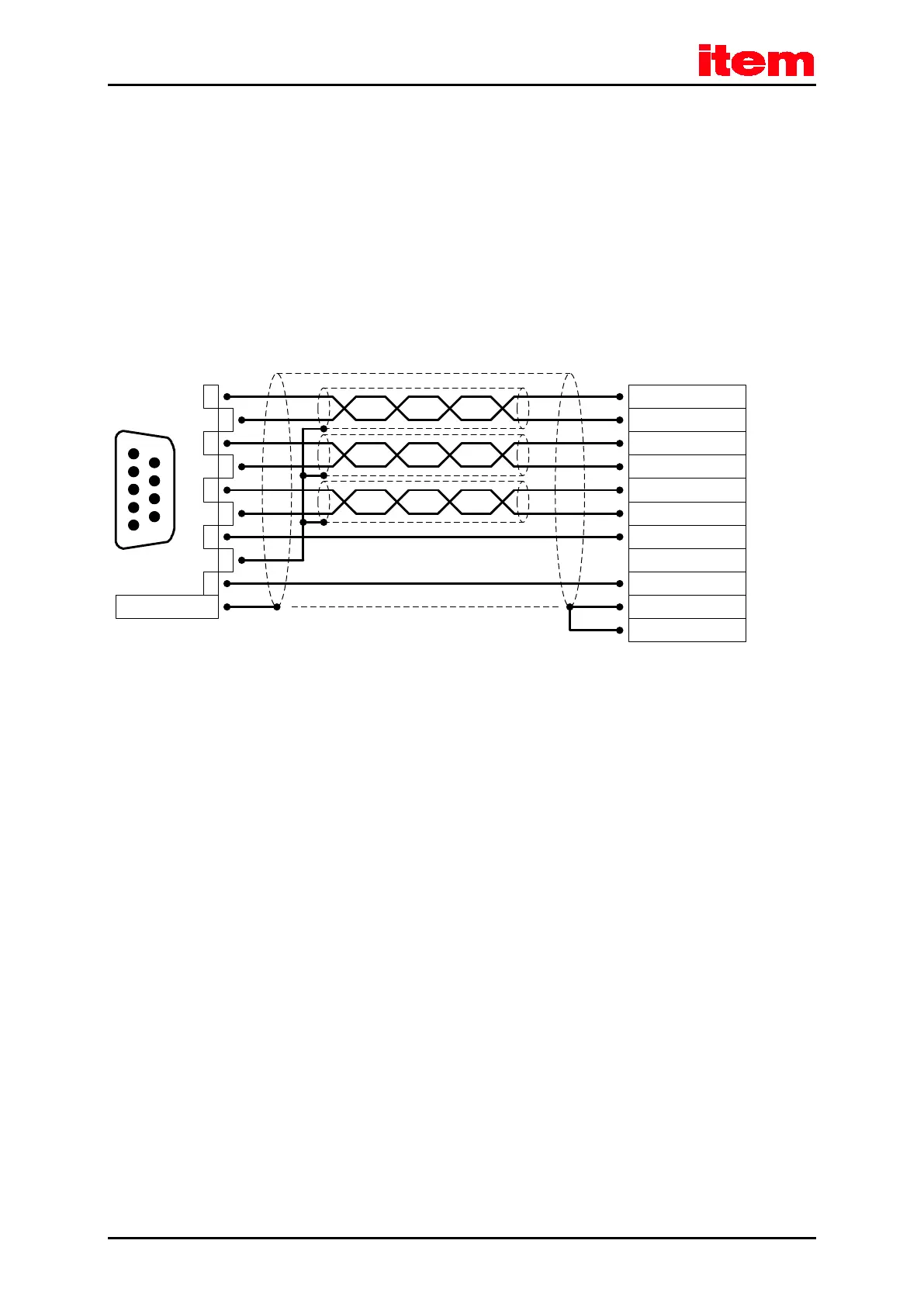
8.9.4 Cable type and configuration [X11]
We recommend using encoder connecting cables in which the incremental encoder signals are twisted in pairs and the
individual pairs are shielded.
8.9.5 Connection notes [X11]
2
3
4
5
6
7
8
1
9
Connector
housing
1
5
9
6
Cable shield
(optional)
B#
B
N
A
N#
GND
VCC
A#
Incremental encoder input
(e.g. item Servo Positioning
Controller C Series, X10)
D-SUB connector
at X11
Incremental encoder output
Male
Connector housing
Figure 24: Pin assignment [X11]: incremental encoder output
The output driver at the signal output provides differential signals (5 V) as per the RS422 interface standard.
Up to 32 additional servo positioning controllers can be controlled by one device.

 Loading...