.
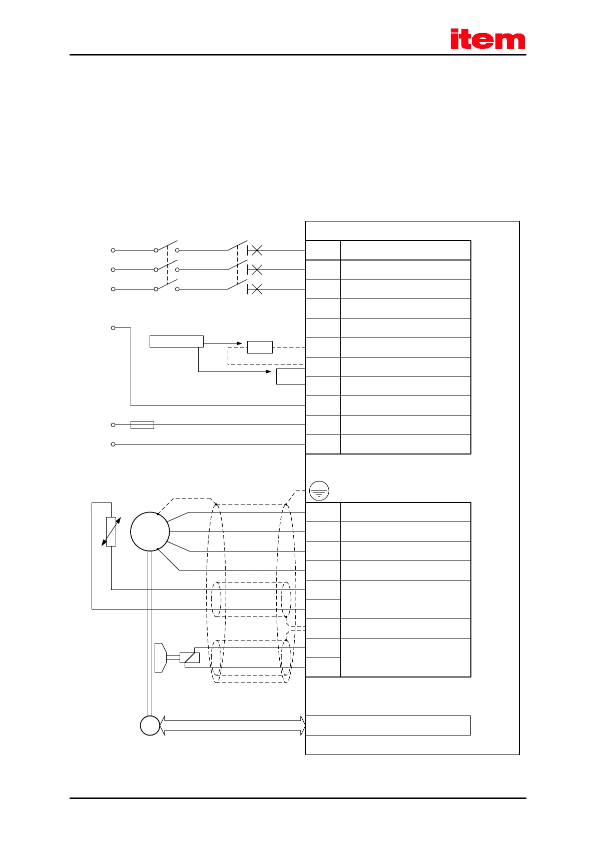
Resolver / Encoder
SM
E
24V / 2A
for the
holding brake
Power Supply [X9]
Motor feedback [X2A] / [X2B]
C 3-Series
24V Supply
Motor feedback
T
Permanent-magnet
synchronous maschine
Shield connection for motor cable
L 3
PE
+24V
0V
F1
External braking
resistor
Bridge for internal
braking resistor
Alternative !
L 2
ZK+ Pos. DC bus voltage
ZK- Neg. DC bus voltage
BR-INT
Connector for internal braking
resistor
BR-CH
Brake chopper connector for
internal/external braking resistor
PE
Protective earth (ground)
conductor
+24V
Supply for control part (1A) and
holding brake (2A)
GND24V Reference potential supply
Mains phase 2
L 3
Motor [X6]
U
Motor phase 2
W Motor phase 3
PE
Protective earth (ground)
conductor of motor
MT+
Motor temperature sensor,
normally closed contact, PTC,
KTY...
MT-
PE
Inner shield connection (holding
brake + temperature sensor)
BR+
BR-
Holding brake (motor), signal level
depending on switching state,
high side/low side switch
Motor phase 1
V
I
L 1
Mains phase 1
Mains phase 3
230VAC ... 480 VAC +/-
10%
L 2
L 1
BR-EXT
Connector for external braking
resistor
Automatic circuit
breaker
 Loading...
