Electrical installation
Page 80
8.4 Connector: motor [X6]
8.4.1 Configuration on the device [X6]
PHOENIX Power-COMBICON PC 4/9-G-7.62 BK
8.4.2 Mating connector [X6]
PHOENIX Power-COMBICON PC 4 HV/9-ST-7.62 BK
8.4.3 Pin assignment [X6]
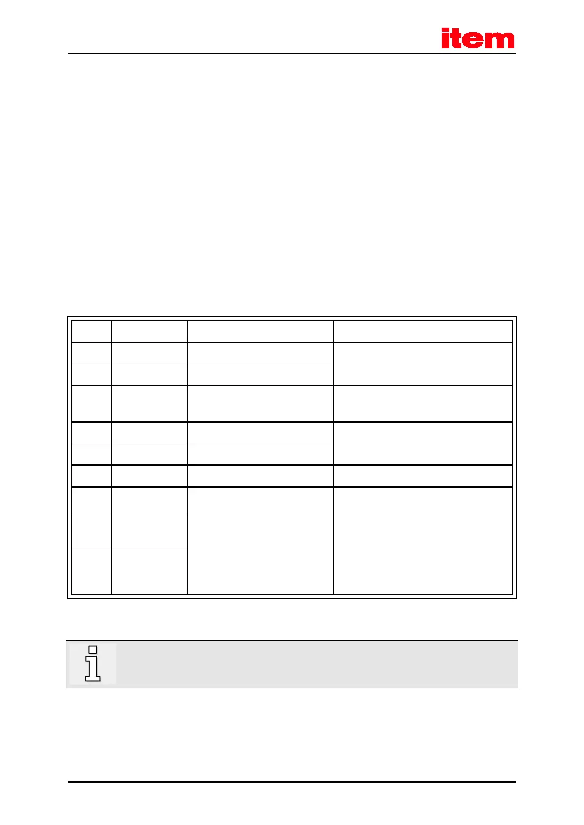
Table 35: Pin assignment [X6]
1 BR- 0 V brake
Holding brake (motor), signal level depending on
the switching state, high-side/low-side switch
2 BR+ 24 V brake
3 PE PE Inner shield connection (holding brake +
temperature sensor)
4 MT- GND
Motor temperature sensor
1)
, normally closed
contact, normally open contact, PTC, NTC, KTY
5 MT+ + 3.3 V/5 mA
6 PE PE
Protective earth (ground) conductor of the motor
7 W 0 ... 360 V
RMS
0 ... 5 A
RMS
0 ... 10 A
RMS
0 ... 1000 Hz
C 3-05
C 3-10
Connection of the three motor phases
8 V
9 U
1)
Please refer to
chapter 9 Additional requirements to be fulfilled by the servo positioning controllers for UL approval
,
page 113.
In addition, the outer cable shield of the motor cable must be connected to the mounting plate of the
controller over a large contact area with the aid of shield terminal SK14.

 Loading...