Mechanical installation
Page 72
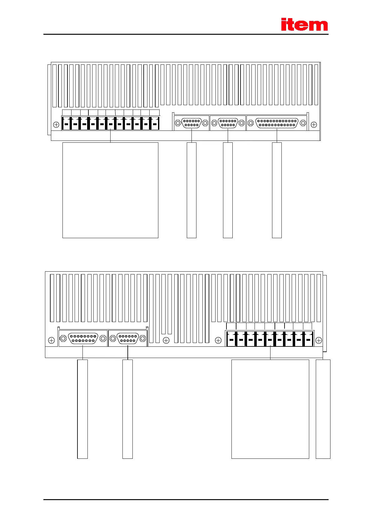
[X
11]: Incremental encoder output
[X
10]: Incremental encoder input
[X1]: I/O interface
[X1] I/O[X10] IN[X11] OUT
[X9.]
PE
BR-INTBR-CH
BR-EXT
ZK-ZK+L3L2L1
+24V GND24V
[
X9]: Power Supply
L 1: mains phase 480VAC
L 2: mains phase 480VAC
L 3: mains phase 480VAC
ZK+: pos. DC bus voltage
ZK-: neg. DC bus voltage
BR-EXT: external brake chopper
BR-CH: brake chopper
BR-INT: internal brake chopper
PE: ground conductor from
mains
+24V: 24VDC
GND24V: GND 24VDC
Figure 10: item Servo Positioning Controller C 3-05: view from above
[X
6]: Motor Connection
BR-: holding brake
BR+: holding brake
PE: connection for inner shield
(holding brake + temperature sensor)
MT-: motor sensor
MT+ motor sensor
PE:
protective earth (ground) conductor
W: motor phase 3
V: motor phase 2
U: motor phase 1
[X2A]: Connection for the resolver
[X2B]: Connection for the encoder
[X6.]
[X2A] RESOLVER[X2B] ENCODER
UVWPEMT+MT-PEBR+BR-
Fastening bracket of shield connection
terminal block SK14
Figure 11: item Servo Positioning Controller C 3-05: view from below

 Loading...