Electrical installation
Page 79
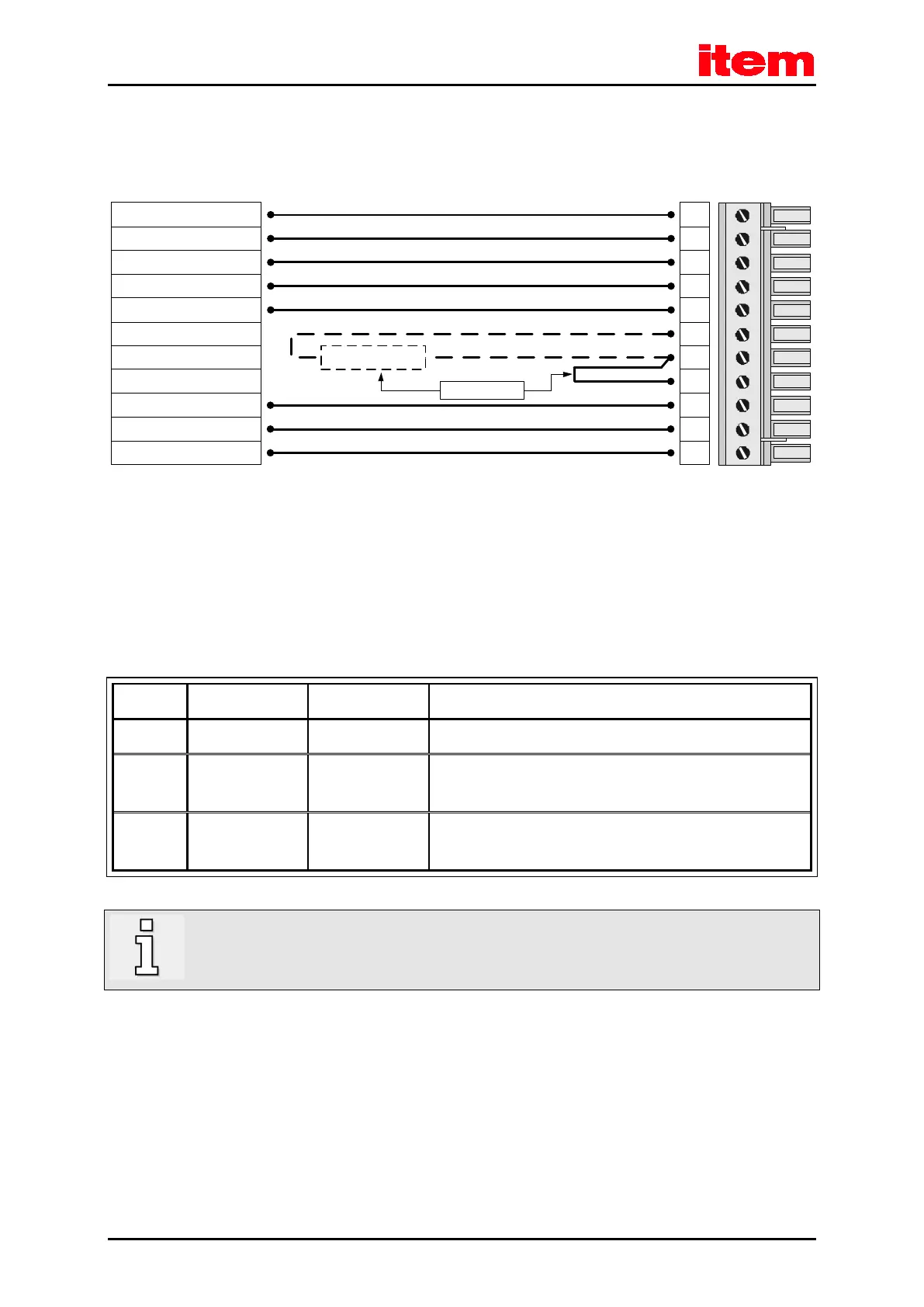
8.3.5 Connection notes [X9]
PHOENIX COMBICON
at [X9]
1
4
7
9
2
5
8
3
Power connector
6
BR-CH
L1
L2
L3
PE
BR-INT
ZK-
BR-EXT
ZK+
GND24V
+24V
11
10
external braking
resistor
Alternative!
Figure 15: Power supply [X9]
The item Servo Positioning Controller C 3-Series has an internal brake chopper and braking resistor. For more braking power,
an external braking resistor can be connected to the [X9] pin-and-socket connector.
Table 34: Pin-and-socket connector [X9]: external braking resistor
6 BR-EXT < 800 VDC Connection of the external braking resistor
7 BR-CH < 800 VDC Brake chopper connection for the internal braking resistor against
BR-INT and for the external braking resistor against BR-EXT
8 BR-INT < 800 VDC Connection of the internal braking resistor
(bridge to BR-CH when using the internal resistor)
If no external braking resistor is used, a bridge must be connected between PIN 7 and PIN 8 so that the
precharging of the DC bus circuit at mains power "ON" and the rapid discharge of the DC bus circuit are
operational!

 Loading...