Electrical installation
Page 88
8.6 Connector: resolver [X2A]
8.6.1 Configuration on the device [X2A]
D-SUB connector, 9-pin type, female
8.6.2 Mating connector [X2A]
D-SUB connector, 9-pin type, male
Housing for a 9-pin D-SUB connector with locking screws of type 4/40 UNC
8.6.3 Pin assignment [X2A]
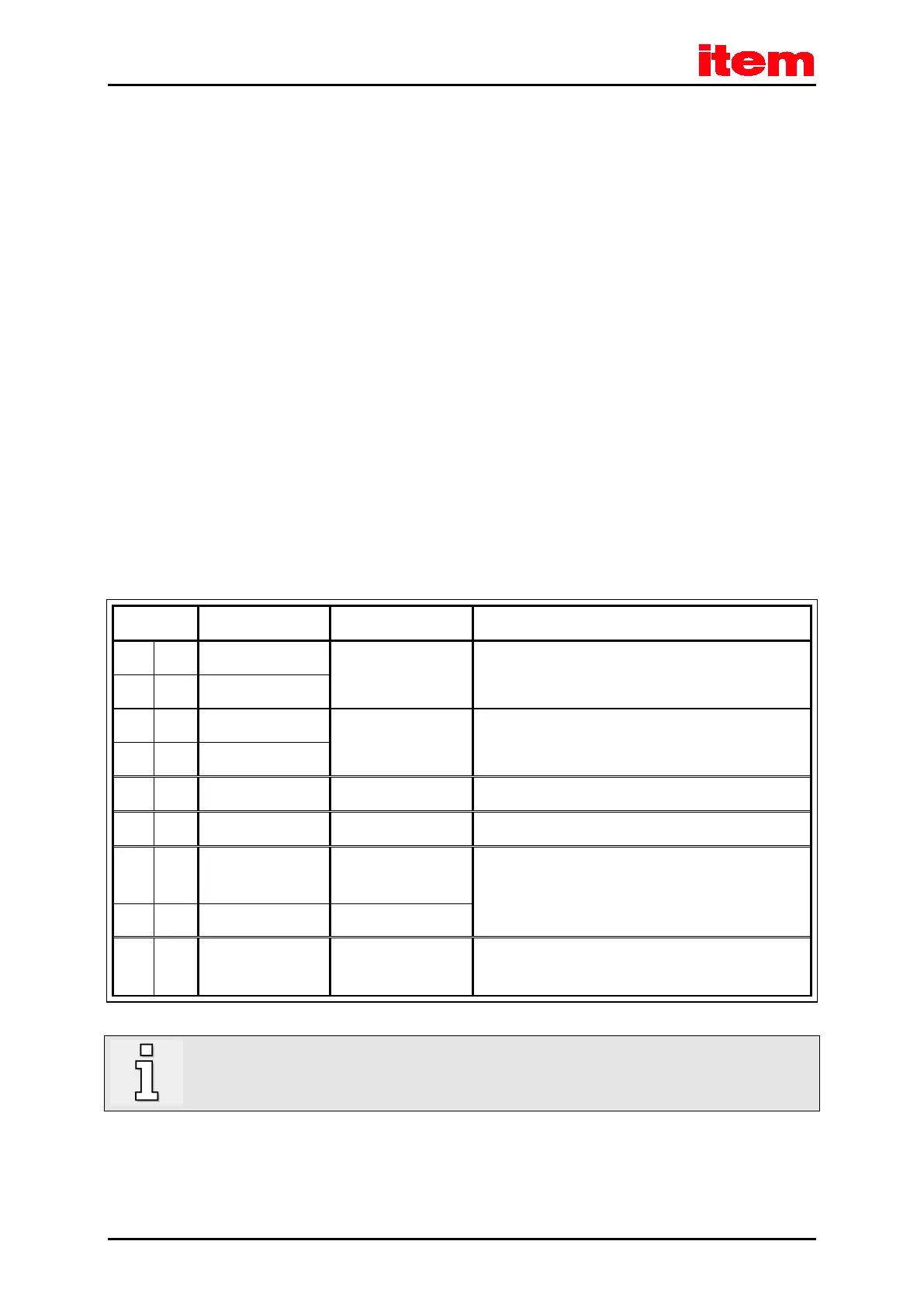
Table 37: Pin assignment [X2A]
1 S2 3.5 V
RMS
/ 5-10 kHz
R
i
> 5 kΩ
SINE track signal, differential
6 S4
2 S1 3.5 V
RMS
/ 5-10 kHz
R
i
> 5 kΩ
COSINE track signal, differential
7 S3
3 AGND 0 V Shield for signal pairs (inner shield)
8 MT- GND Temperature sensor reference potential
4 R1 7 V
RMS
/ 5-10 kHz I
out
≤ 150 mA
RMS
Carrier signal for the resolver
9 R2 GND
5 MT+ + 3.3 V / Ri = 2 kΩ
Motor temperature sensor, normally closed contact, PTC,
KTY…
In addition, the outer cable shield of the angle encoder cable must be connected to the mounting plate of the
controller over a large contact area with the aid of shield terminal SK14.

 Loading...