Electrical installation
Page 78
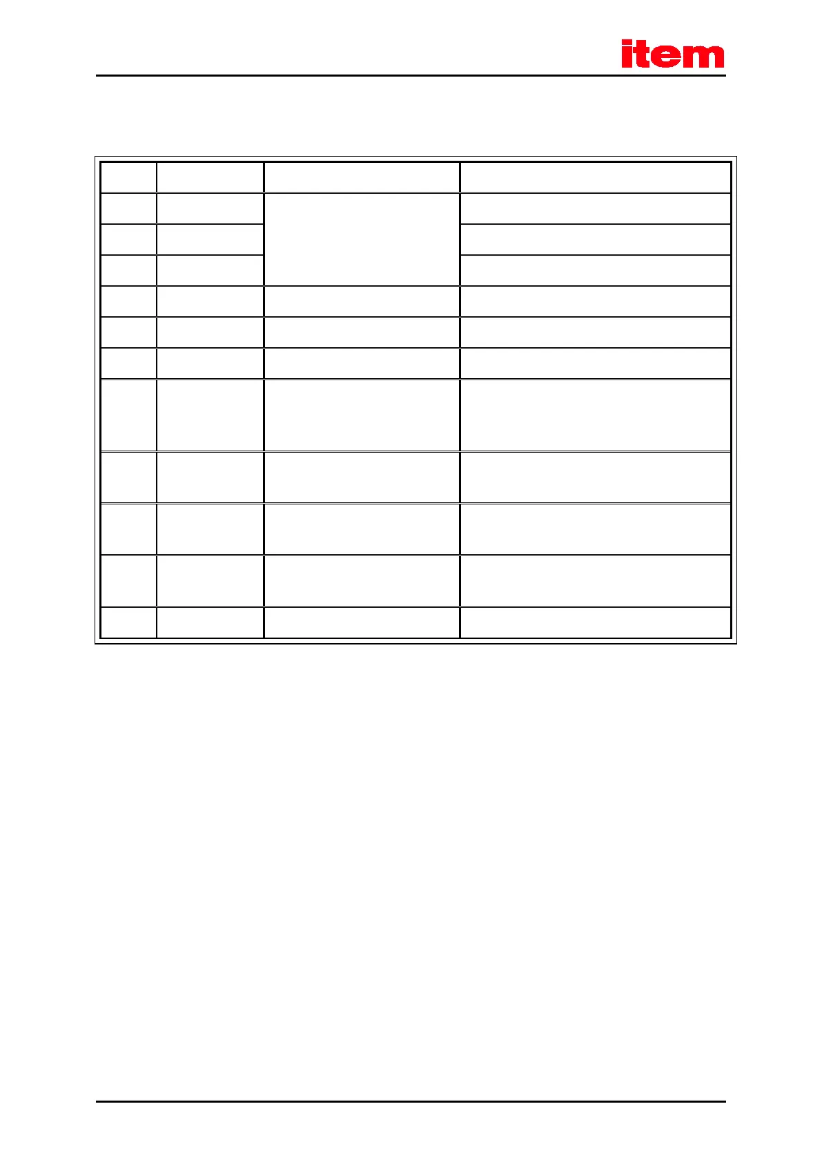
8.3.3 Pin assignment [X9]
Table 33: Pin assignment [X9]
1 L1 230 ... 480 VAC [± 10%],
50 ... 60 Hz
Mains phase 1
2 L2 Mains phase 2
3 L3 Mains phase 3
4 ZK+ < 700 VDC Pos. DC bus circuit voltage
5 ZK- GND_ZK Neg. DC bus circuit voltage
6 BR-EXT < 800 VDC Connection of the external braking resistor
8 BR-CH < 800 VDC Brake chopper, connection for the internal braking
resistor against BR-INT or of the external braking
resistor against ZK+
7 BR-INT < 800 VDC Connection of the internal braking resistor
(bridge to BR-CH when using the internal resistor)
9 PE PE Connection of the protective earth (ground)
conductor of the mains power supply
10 +24 V 24 VDC [± 20%], 1 A
*)
Supply voltage for the control module and holding
brake
11 GND24V GND (0 VDC) Supply voltage reference potential
*)
plus the current consumption of a holding brake and I/Os (if included)
8.3.4 Cable type and configuration [X9]
The cable names that are stated refer to cables made by Lapp. They have proved to be reliable and are successfully used in
many applications. However, it is also possible to use comparable cables from other manufacturers, for example Lütze or
Helukabel.
For the 400 V supply:
LAPP KABEL ÖLFLEX CLASSIC 110; 4 x 1.5 mm²

 Loading...