Electrical installation
Page 91
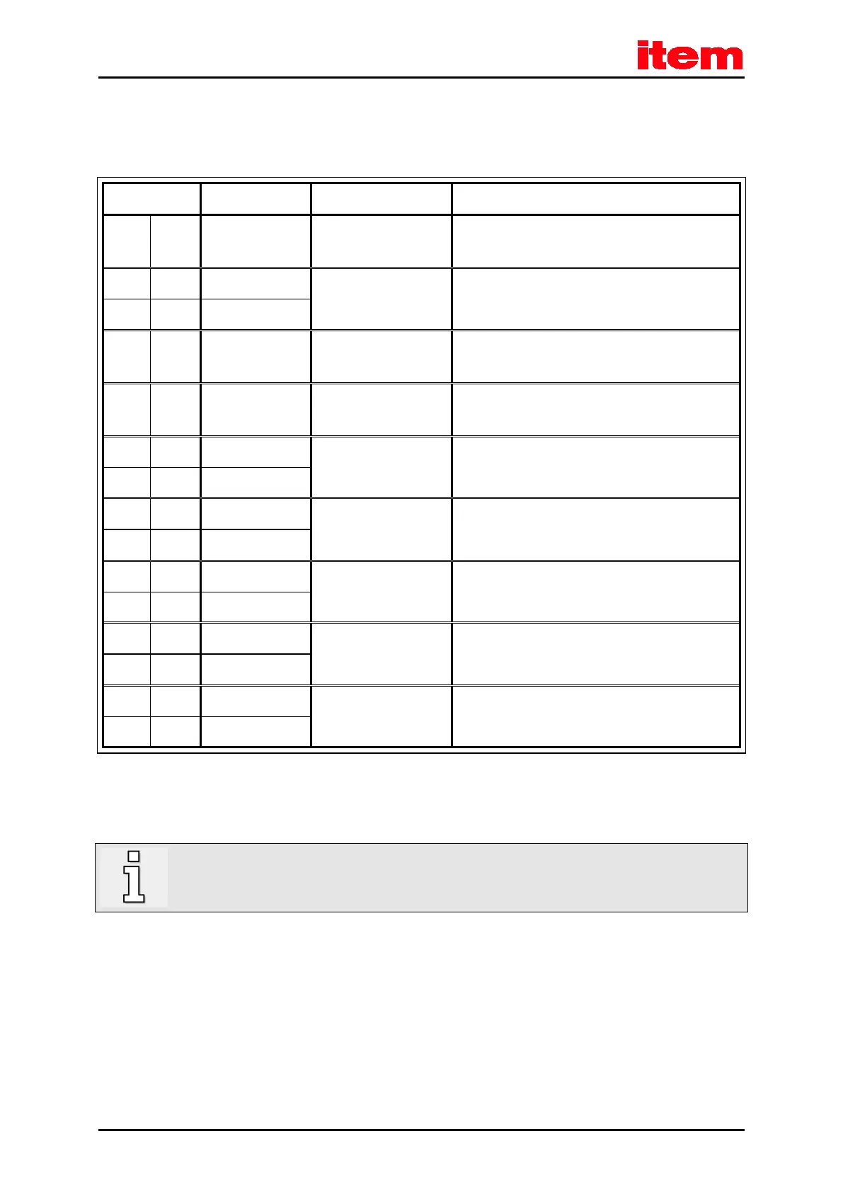
8.7.3 Pin assignment [X2B]
Table 38: Pin assignment: analogue incremental encoder – option [X2B]
1 MT+ + 3.3 V / Ri = 2 kΩ Motor temperature sensor
1)
, normally closed contact,
PTC, KTY ...
9 U_SENS+ 5 V ... 12 V
R
I
≈ 1 kΩ
Sensor cables for the encoder supply
2 U_SENS-
10 US 5 V / 12 V / ± 10%
I
max
= 300 mA
Operating voltage for high-resolution incremental
encoders
3 GND 0 V Reference potential for the encoder supply and motor
temperature sensor
11 R 0.2 V
pp
… 0.8 V
pp
RI ≈ 120 Ω
Index pulse track signal (differential) of the high-
resolution incremental encoder
4 #R
12 COS_Z1
2)
1 V
pp
/ ± 10%
RI ≈ 120 Ω
COSINE commutation signal (differential) of the high-
resolution incremental encoder
5 #COS_Z1
2)
13 SIN_Z1
2)
1 V
pp
/ ± 10%
RI ≈ 120 Ω
SINE commutation signal (differential) of the high-
resolution incremental encoder
6 #SIN_Z1
2)
14 COS_Z0
2)
1 V
pp
/ ± 10%
RI ≈ 120 Ω
COSINE track signal (differential) of the high-
incremental encoder
7 #COS_Z0
2)
15 SIN_Z0
2)
1 V
pp
/ ± 10%
RI ≈ 120 Ω
SINE track signal (differential) of the high-resolution
incremental encoder
8 #SIN_Z0
2)
1)
Please refer to
chapter 9 Additional requirements to be fulfilled by the servo positioning controllers for UL approval
,
page 113.
2)
Heidenhain encoder: A=SIN_Z0; B=COS_Z0; C=SIN_Z1; D=COS_Z1
In addition, the outer cable shield of the angle encoder cable must be connected to the mounting plate of the
controller over a large contact area with the aid of shield terminal SK14.
 Loading...
