Electrical installation
Page 93
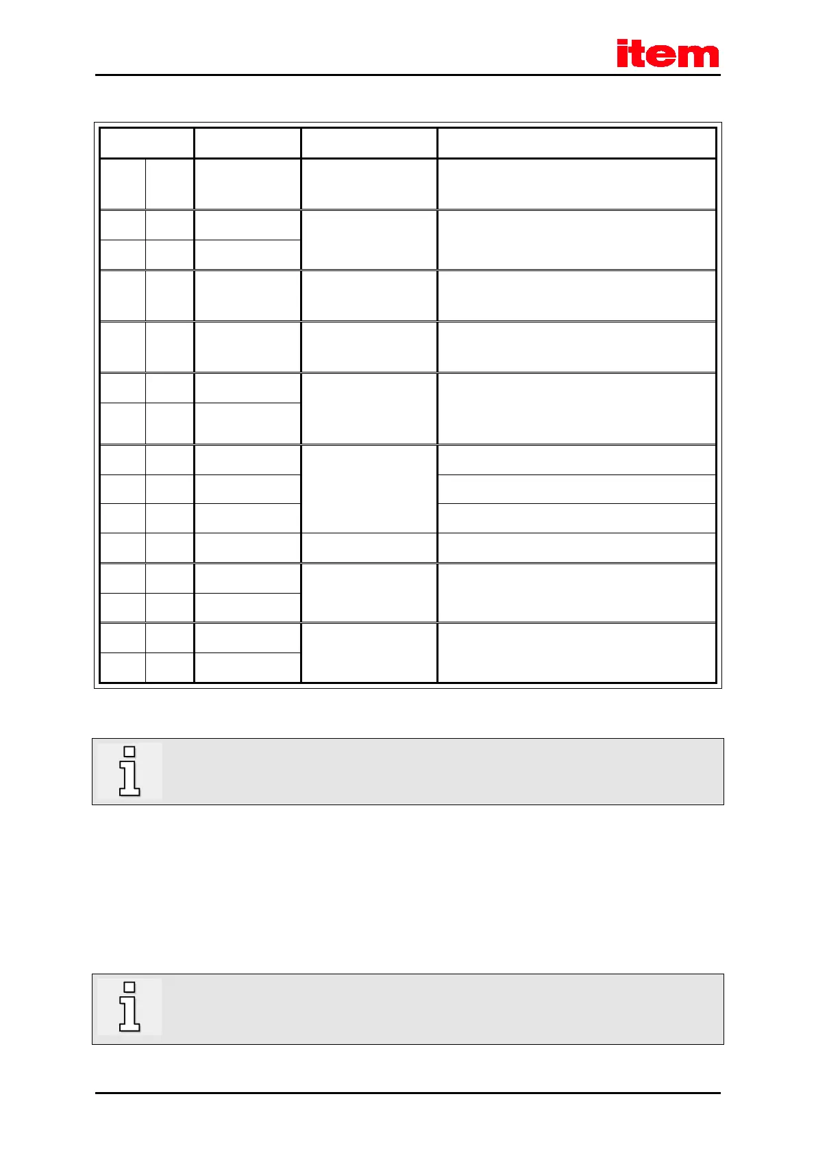
Table 40: Pin assignment: digital incremental encoder – option [X2B]
1 MT+ + 3.3 V / Ri = 2 kΩ Motor temperature sensor
1)
, normally closed contact,
PTC, KTY ...
9 U_SENS+ 5 V ... 12 V
R
I
≈ 1 kΩ
Sensor cables for the encoder supply
2 U_SENS-
10 US 5 V / 12 V / ± 10%
I
max
= 300 mA
Operating voltage for high-resolution incremental
encoders
3 GND 0 V Reference potential for the encoder supply and motor
temperature sensor
11 N 2 V
pp
… 5 V
pp
RI ≈ 120 Ω
Index pulse RS422 (differential)
of the digital incremental encoder
4 #N
12 H_U 0 V / 5 V
RI ≈ 2 kΩ
on VCC
Phase U of the Hall sensor for commutation
5 H_V Phase V of the Hall sensor for commutation
13 H_W Phase W of the Hall sensor for commutation
6
14 A 2 V
pp
… 5 V
pp
RI ≈ 120 Ω
A track signal RS422 (differential)
of the digital incremental encoder
7 #A
15 B 2 V
pp
… 5 V
pp
RI ≈ 120 Ω
B track signal RS422 (differential)
of the digital incremental encoder
8 #B
1)
Please refer to
chapter 9 Additional requirements to be fulfilled by the servo positioning controllers for UL approval
,
page 113.
In addition, the outer cable shield of the angle encoder cable must be connected to the mounting plate of the
controller over a large contact area with the aid of shield terminal SK14.
8.7.4 Cable type and configuration [X2B]
We recommend using the encoder connecting cables that have been approved for the product in question by the
corresponding manufacturer (Heidenhain, Sick-Stegmann, etc.). If the manufacturer does not recommend a particular cable,
we recommend configuring the encoder connecting cables as described below.
For the angle encoder supply US and GND, we recommend a minimum cross-section of 0.25 mm² for an
angle encoder cable length up to 25 m, and a minimum cross-section of 0.5 mm² for an angle encoder cable
length up to 50 m.

 Loading...