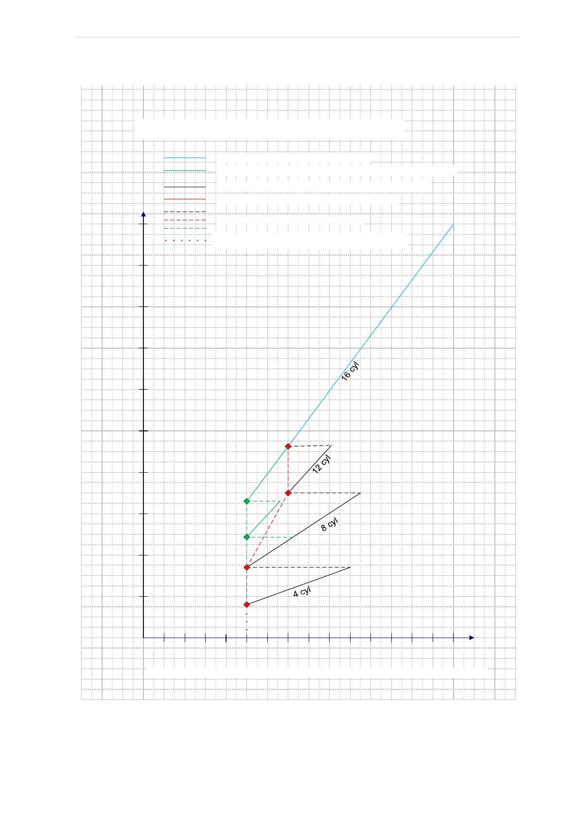
Fig. 19: Capacity vs speed diagram, SMC 116 E with CFA 30/90 coupling.
Capacity vs speed diagram , SMC 11 6 E VSD w ith C F A30/90 coupling
Minimum speed: 500 rpm
Speed (rpm)
Capacity %
005100010050
0
1 0
2 0
3 0
4 0
5 0
6 0
7 0
8 0
9 0
10 0
Black li n e : S P E E D mo d e (op t i mi sed f o r be st r egula t i on)
Red line: S T EP mode (optimised for best COP)
4 cyl
8 cyl
Blue line: both SPEEDand STEP mode
Dashed lines: transient operation only
Note: Actual allowed speed range depends on operating conditions and motor selection.
12 cyl
16 cyl
Dotted red line: regulation by utilising total
unloading and/or compressor start/stop
Green line: requires a motor able to give fulltorque at 500 rpm
16 cyl
12 cyl

 Loading...

