Engineering manual - UniSAB III 1.10.8
268/346
001930 en 2021.06
Calibration
7.5.11 Adjusting short-stroke volume transmitter for SAB 193-233-283 and SAB 355
Note: The transmitter cannot be calibrated. Software calibration in UniSAB III must be used.
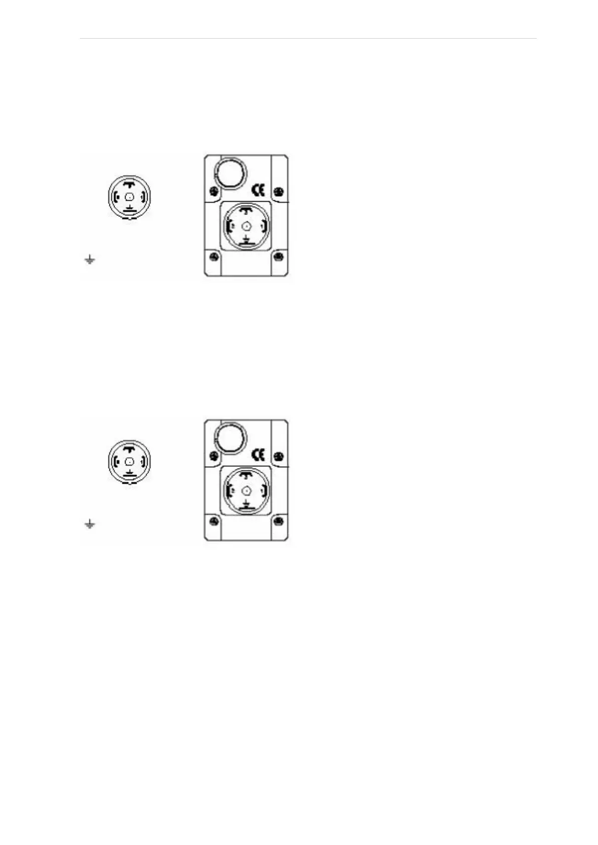
Terminal connection is shown in Fig. 39.
Fig. 39: Terminal connection
Follow the instruction in subsection 7.5.5 Volume ratio slide adjustment, auto Vi and subsection 7.5.14
Software calibration, hydraulic slide systems
7.5.12 Adjusting short-stroke capacity rod for SAB 120 and SAB 151
Note: The transmitter cannot be calibrated. Software calibration in UniSAB III must be used.
Terminal connection is shown in Fig. 40.
Fig. 40: Terminal connection
Note: As the compressors are equipped with auto Vi (controlled in 3 steps), follow the instruction in sub-
section 7.5.4 Capacity slide adjustment, auto Vi and subsection 7.5.14 Software calibration, hydraulic
slide systems
7.5.13 Adjusting long-stroke capacity rod for SAB 193 H-233 H-283 H-355 H
For part no. 1373.2021
Normal operation
When the sensor is mounted and operating, the compressor capacity is indicated. The position is indi-
cated in a range of 0-100%, corresponding to 4-20 mA.
As shown in Fig. 41, the capacity transmitter is fitted with a single calibration button and a green and red
LED on each side.
DIN plug connection
Plug connection
1= Supply, 24V DC
2= Common 0V DC
3= Out 4-20 mA
= GND
Plug connection
1= Supply, 24V DC
2= Common 0V DC
3= Out 4-20 mA
= GND

 Loading...

