Engineering manual - UniSAB III 1.10.8
160/346
001930 en 2021.06
History
I/O
type
No.
Screw
compressors
Reciprocating
compressors
SABCube Chiller
Digital output
1
Compressor motor
start signal
Compressor motor
start signal
(Compressor motor
start signal)
-
2
Oil pump start
signal
Oil rectifier
- -
3 Oil pump 2/cooling
fan start signal
Additional steps
valve B
Water pump start
signal
-
4
- -
POV valve
-
5
Shutdown Shutdown Shutdown
-
6 Alarm Alarm Alarm
-
7 Aux. output Aux. output Aux. output
-
8
Start request (PMS) Start request (PMS) Start request (PMS)
-
9
Capacity down Capacity stage no. 1/
Total unload – addi-
tional steps valve A
- -
10
Capacity up Capacity stage no. 2/
Valve for thermo
pump
- -
11 Volume
Capacity stage no. 3/
Valve for thermo
pump/ Thermo pump
shaft end
SSSTV valve
activate
-
12 Volume up
Capacity stage no. 4/
Thermo pump shaft
end
Vi slide activate
-
13 Economiser - suction
line
Capacity stage no. 5
- -
14 Economiser – liquid
line
Capacity stage no. 6
- -
15
Oil distribution pipe Capacity stage no. 7/
Intermediate liquid
injection
Bypass valve
-
16
Oil cooling (Dual HLI
2 cooling when Vi >
85%)
Oil cooling (oil temp.)
Thermo pump
internal
-
Bypass function
(start unload)/Stop
valve for level control
17 Oil cooling (HLI cool-
ing stop valve)
Water cooling (dis-
charge temp.)
Thermo pump
internal
- -
18
Oil rectifier (Marine) Oil return
-
Oil return from
evaporator
19
- - -
Oil return from
separator
20 Heating elements
- - -
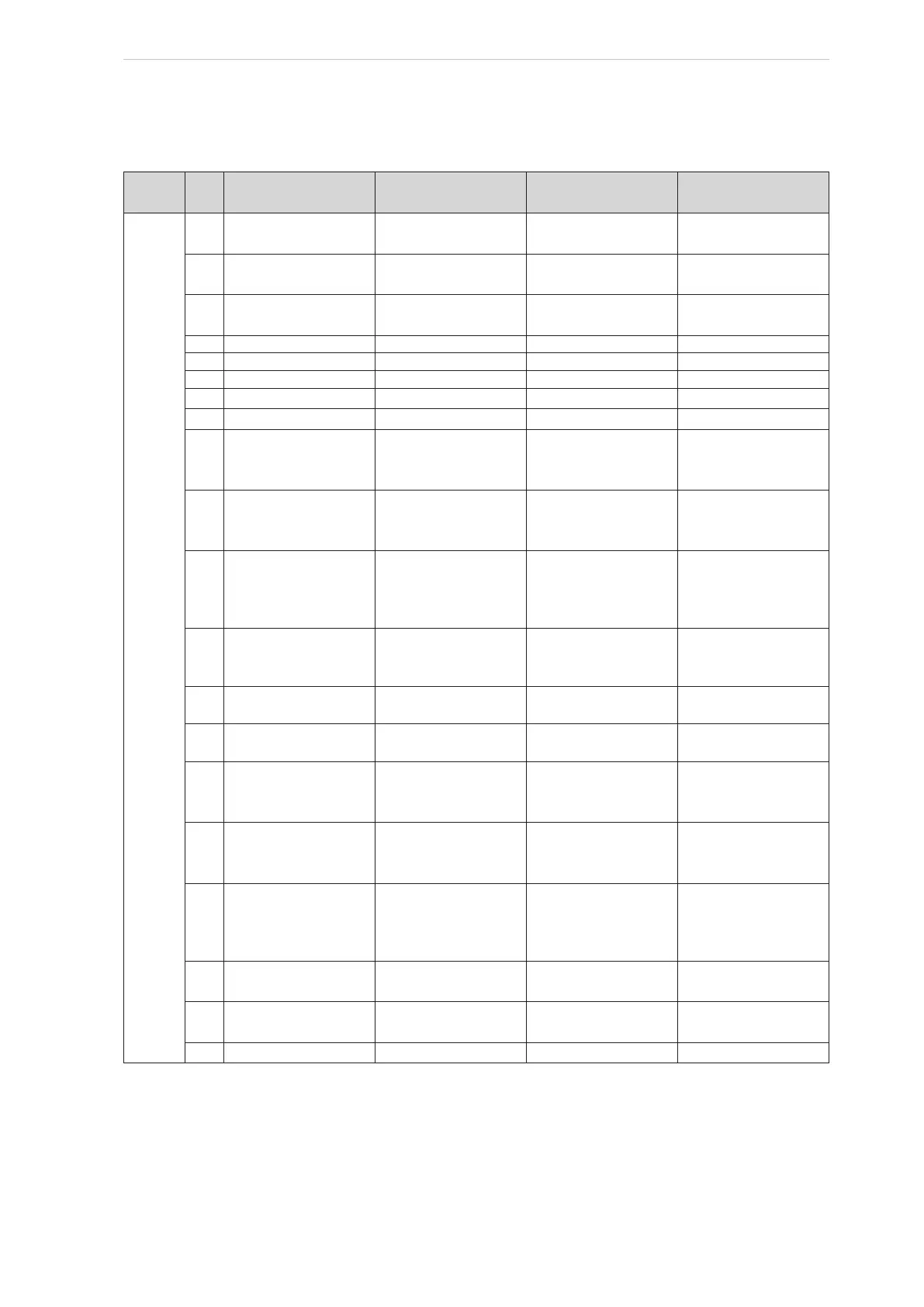
Table 34: Numbering of digital outputs

 Loading...

