Engineering manual - UniSAB III 1.10.8
001930 en 2021.06
75/346
Compressor control and surveillance
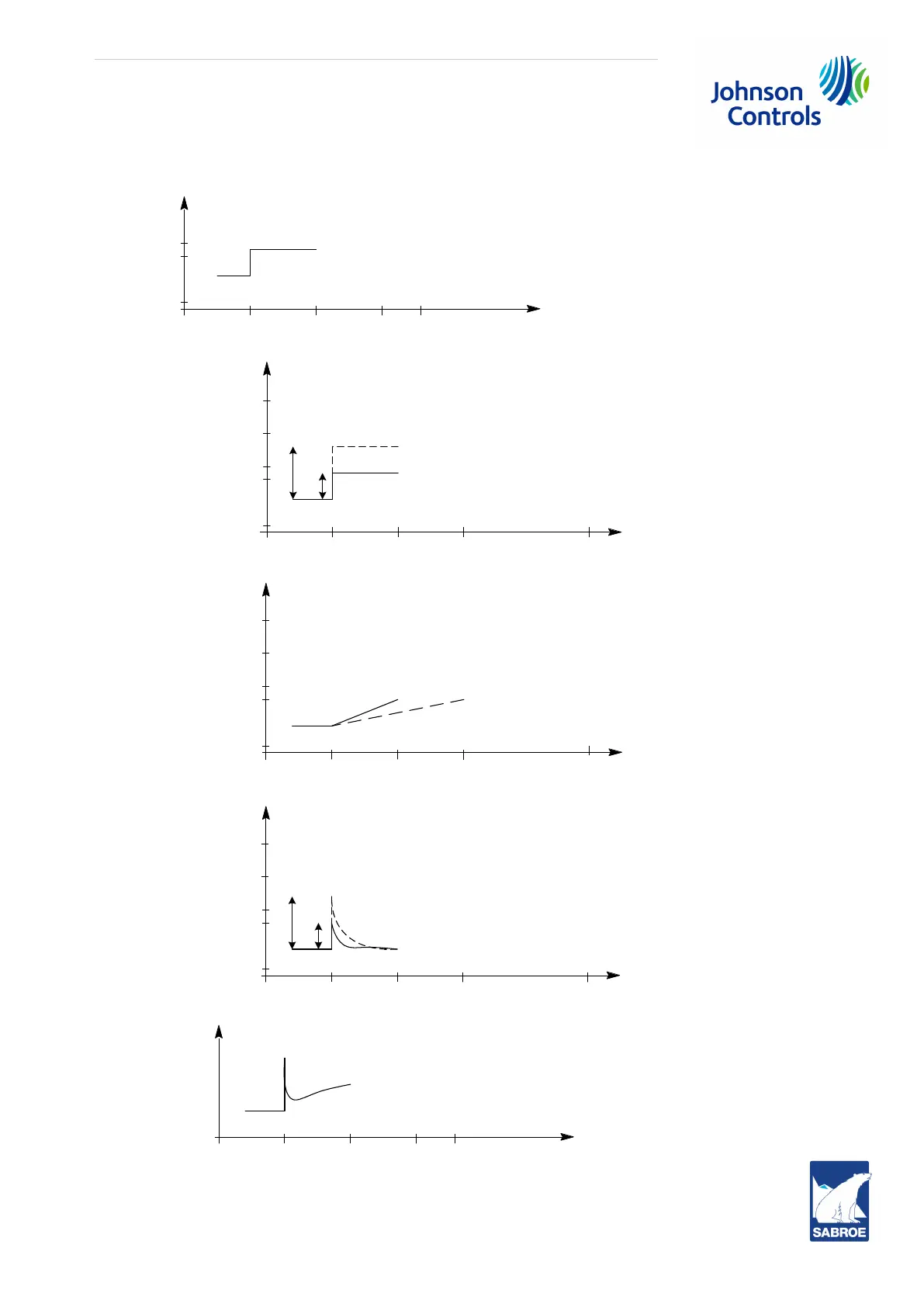
The following diagrams show how the PID regulator reacts on a specific change in the input signal. The
diagrams are divided into P, I and D parts.
%
Time0 5 10 15
B
A
Output signal
P-part
A: Proportional band = 10°C
B: Proportional band =5°C
C
D
%
Time0 5 10 15
Output signal
I-part
C: Integral time = 30 sec
D: Integral time = 60 sec
F
E
Time151050
Output signal
D-part
E: Differential time = 10 sec
F: Differential time = 20 sec
%
%
Time0 5 10 15
Output signal
PID-part

 Loading...

