6-2
6.1.2 Sensor Installation Procedure
The sensor base contains 1 inch-14UNS-2B screw holes. It can be attached to poles with cut
male screws, or off-the-shelf adapters.
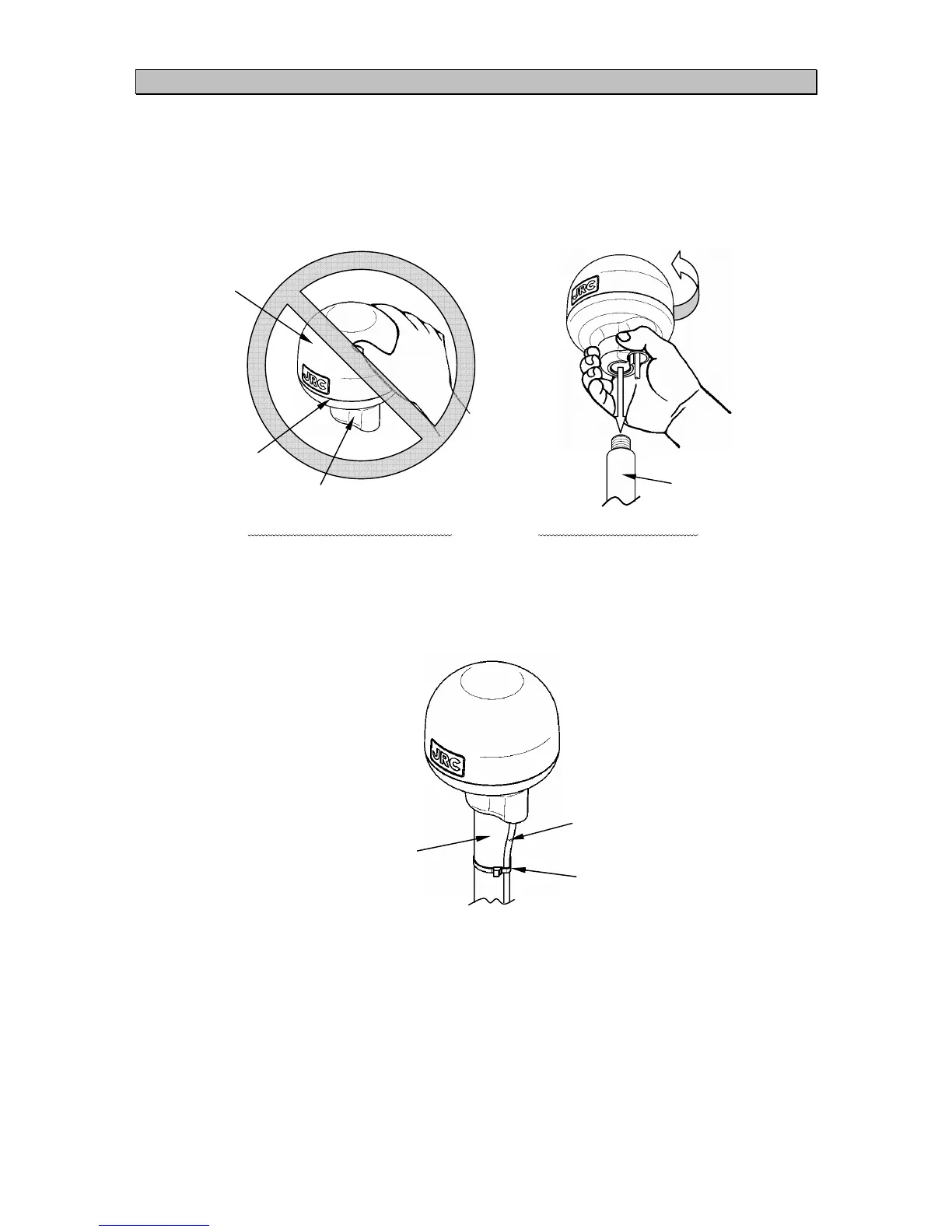
(1) When performing attachment, always hold and turn the sensor base. Holding and turning the
radome may result in a large amount of force applied at the junction of the base and the
radome, resulting in damage to the sensor. The diagram shows the JLR-4341, but these
instructions apply equally to the JLR-4340 as well.
Do not apply force to the joint. Hold and turn the base.
(2) Secure the sensor cable in position with a clamp band as shown below to protect it against
damage due to vibration.
(3) When connecting an extension cable to the DGPS sensor, always seal with self-bonding
tape in order to waterproof the connector, and wrap this section with vinyl tape to protect it.
Radome
Base
Joint
Off-the-shelf
adapter, etc
Off-the-shelf
adapter, etc
Clamp band
Cable