FX-1/FX-1R Maintenance Manual
1-1-3. Adjustment Procedure
(1) Make measurements with a Yunitta's tension meter placed at the positions indicated by the
arrows in the figure below and check to make sure that the values are within the specification
value range.
(Note 1) Measure the belt tension by tapping the center of the belt with a stick. At this
time, put the microphone so that it receives the vibration produced at the center
of the belt in the width direction. (When receiving the vibration produced at both
ends, the measured value may become 30N larger than that obtained at the
center. Strictly observe this point.)
(Note 2) Since the tension of the X- or Y-motor belt may vary depending on the
orientation of the motor pulley, measure the tension at the position shown in
Figure 1-1-4-2.
(2) Tension meter input values
Table 1-1-3-1
Belt type
Belt unit weight
(g/m・mm)
Belt width
(mm)
Belt span
(mm)
Timing belt YM 2.5 40 93
YB belt 3.8 70 988
1-1-4. Measurement Positions and Specification Values
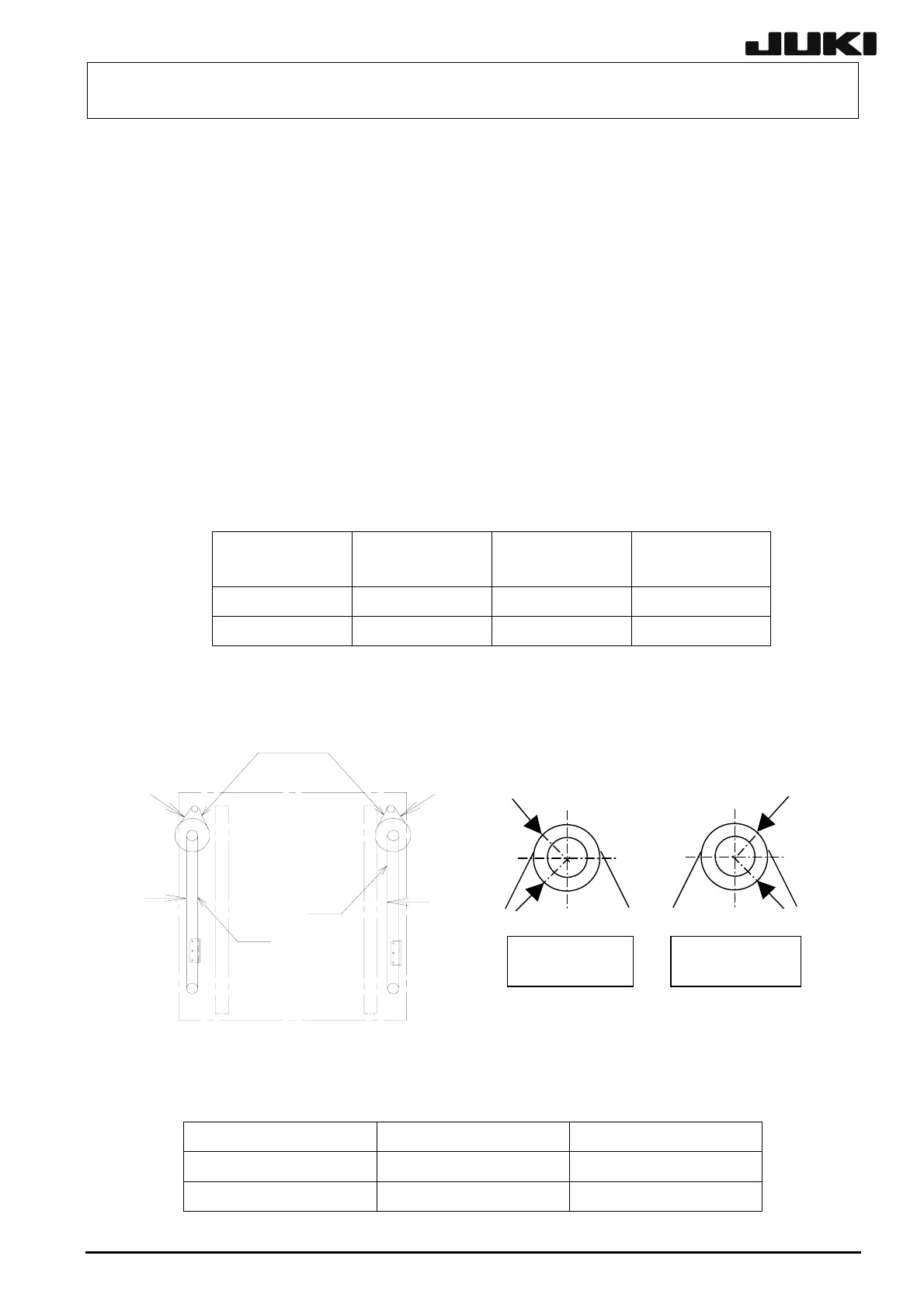
(1) Measure the belt tension at the positions shown in the figure below.
1-3
Figure 1-1-4-1 Figure 1-1-4-2
Table 1-1-4-1
Belt type Factory default setting Readjustment on market
YB BELT
1100 ± 50N
800N or more
TIMING BELT YM
290 ± 50N
160N or more
Measure and adjust the tension at the setscrew
position A or B.
Pulley set screw
position B
Pulley set screw
position A
Front
Y-belt
Y-belt
Rear
Y-axis
X-motor belt
Rev. 2.00