FX-1/FX-1R Maintenance Manual
13-6-2. LED Indications
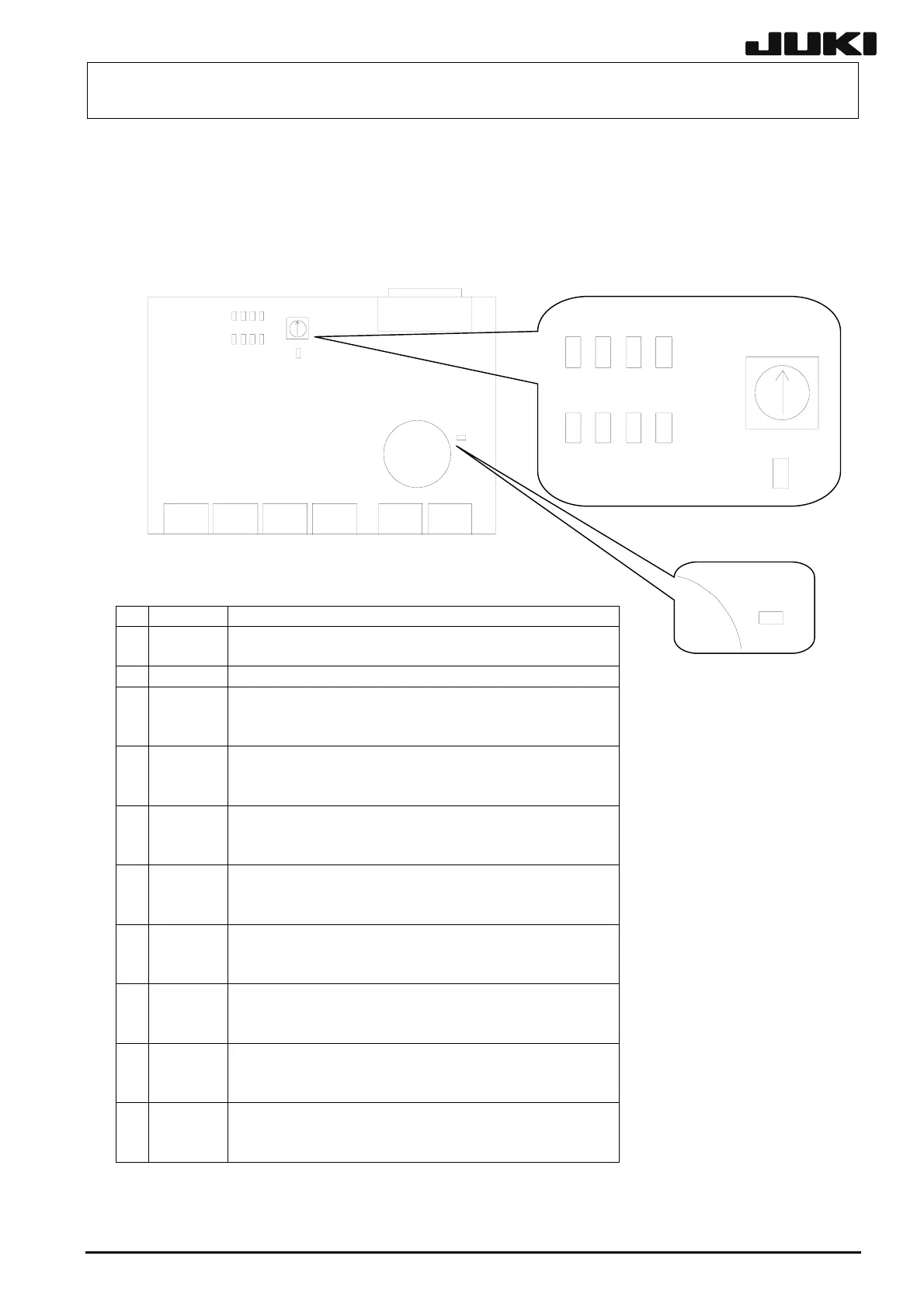
Ten LEDs are mounted on the 4-axis integral amplifier.
These LEDs show the operating status of the 4-axis integral amplifier as shown below.
13-26
No. LED name Function
1 CHARGE Lights up if electric charge exists in the main power supply.
Do not joint the electric wire when this LED is lit.
2 SRD Lit when the control power (DC5V) is supplied correctly.
3 RD1 Shows the status of the 1st axis.
Flashing in green: Servo OFF status
Lit in green: Servo ON status
4 AL1 Shows the status of the 1st axis.
Flashing in red: Warning status
Lit in red: Alarm status
5 RD2 Shows the status of the 2nd axis.
Flashing in green: Servo OFF status
Flashing in red: Warning status
6 AL2 Shows the status of the 2nd axis.
Flashing in red: Warning status
Lit in red: Alarm status
7 RD3 Shows the status of the 3rd axis.
Flashing in green: Servo OFF status
Lit in green: Servo ON status
8 AL3 Shows the status of the 3rd axis.
Flashing in red: Warning status
Lit in red: Alarm status
9 RD4 Shows the status of the 4th axis.
Flashing in green: Servo OFF status
Lit in green: Servo ON status
10 AL4 Shows the status of the 4th axis.
Flashing in red: Warning status
Lit in red: Alarm status
AL4 AL3 AL2 AL1
RD4 RD1RD2RD3
SRD
CHARGE
Rev. 2.00