FX-1/FX-1R Maintenance Manual
2-2-2. θ-Motor (MNLA Head)
After the motor has been replaced, it is absolutely necessary to re-input the MS parameters related
to the axis home. (For details of input items, see section 2-9.)
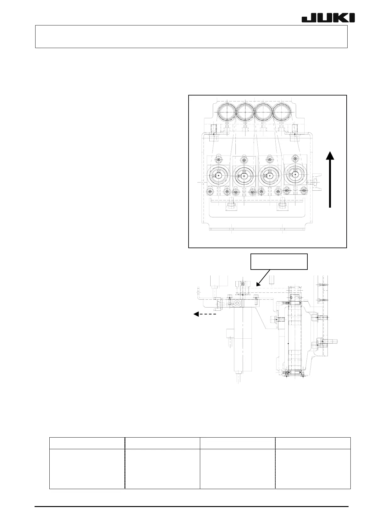
(1) Follow the steps (1) to (5) described in
section 2-1-1 to remove components c
to f.
(2) Detach the Z-motor cover (Four
mounting screws)
(3) Remove the θ-motor mounting screws (3
pcs.) and slide the θ-motor in the
direction indicated by an arrow to loosen
the belt.
2-6
(4) Loosen two setscrews of the pulley, pull
out the θ-motor pulley and detach the
θ-motor.
(5) Reassemble the components in the
reverse order of disassembly.
(6) Check the tension of the belt following
the procedure described on the next
page and make adjustments if
necessary.
Fi
ure 2-2-3
Pull
Figure 2-2-4
Timin
belt θ
<Procedure>
c Put the jig (hook pin) in the tap of the
θ-motor and lock the mounting screw
with the jig pulled in the direction
indicated by an arrow with a force of
21.6 N (2.2 kgf) using a tension rod.
d Using a tension gauge, check that the
belt tension is in a proper tension
range of 10.5 ±1N.
Tension gauge set values
Weight: 0.9 g/m
Width: 6 mm
Span: 64.5 mm
Apply Loctite 242 to the θ-motor
mounting screws (4 pcs.) and tighten
them with a tightening torque of 2.3 Nm.
When tightening the setscrew of the
θ-motor pulley, make sure to align the orientation of the flat part of the θ-motor shaft and
the setscrew of the pulley. Tighten the setscrew with a torque of 0.5 Nm.
Table 2-2-2-1
Part name Part No. Part name Part No.
LT1-MOTOR CABLE ASM
LT2-MOTOR CABLE ASM
LT3-MOTOR CABLE ASM
LT4-MOTOR CABLE ASM
L815E6210A0
L815E8210A0
L816E0210A0
L816E2210A0
RT1-MOTOR CABLE ASM
RT2-MOTOR CABLE ASM
RT3-MOTOR CABLE ASM
RT4-MOTOR CABLE ASM
L816E4210A0
L816E6210A0
L816E8210A0
L817E0210A0
Rev. 2.00