FX-1/FX-1R Maintenance Manual
5-8-2. Replacing the Amplifier Unit
5-8-2-1. Attaching the fiber to the amplifier
(1) Using a finger nail or slotted screwdriver, raise the lever on the top of the
amplifier unit slightly.
(2) Insert the fiber into the amplifier unit completely and push down the lever.
Always attach the light emission and light receiving fibers to their
correct positions. If the fibers are attached to incorrect
positions, the disturbance light may be detected, causing
the sensor to malfunction.
c
e
d
f
The end of the fiber sensor must be cut with the cutter
supplied with the sensor to adjust the length.
5-8-2-2. How to mount the amplifier unit
Mount the amplifier unit using the special mounting bracket (accessory).
(1) Insert the special mounting bracket e into the groove c on the front of
the amplifier unit.
(2) Push the groove d on the rear of the amplifier unit to fit it completely.
Figure 5-8-2-1
(3) To detach the amplifier unit, insert a screwdriver into the groove f and
raise the amplifier unit while pulling it backward.
5-8-2-3. How to adjust the gain of the amplifier unit
After the WAIT sensor has been replaced, follow the steps below to
adjust the gain.
(1) Change the L-ON/D-ON setting switch to D-ON.
5-11
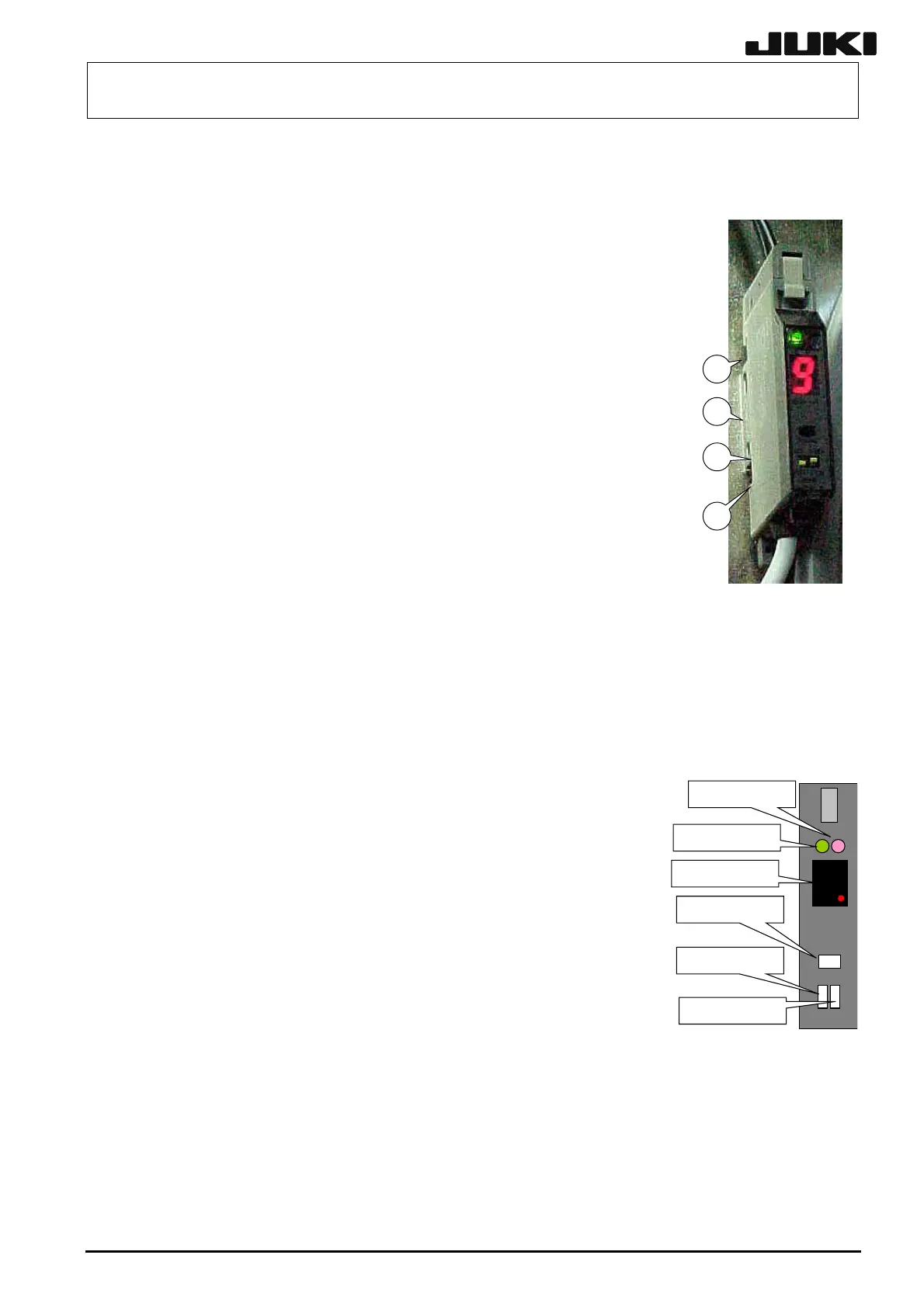
(2) Set the mode setting switch on the amplifier to SET.
The LED indicator on the amplifier shows 1. Red: Not lit, Green: Not
lit.
9
チ
L-ON/D-ON
切替えSW
L-ON/D-ON
setting switch)
モード切替えSW
Mode setting switch
ューニングボタン
Tuning button
デジタル表示器
Digital display
安全表示灯(緑)
Safety LED (green)
動作表示灯(赤)
Operation LED (red)
(3) Place a circuit board at a position where it interrupts the light to the
sensor and press the tuning button. The LED indicator on the
amplifier shows 2. Red: Not lit, Green: Blinks (The red LED blinks
in the case of sensitivity failure.)
(4) Remove the circuit board and press the tuning switch without
interrupting of the light to the sensor. When the gain is adjusted
successfully, the numeric value is shown. This value means the
detection margin and is normally 9. If 9 is not shown, repeat the gain
adjustment again.
Figure 5-8-2-2
(5) Return the amplifier mode setting switch to RUN.
Rev. 2.00
 Loading...


