FX-1/FX-1R Maintenance Manual
The cable assemblies shown in the table below are to be added in automatic PWB width adjustment
motor option.
Connect them according to the instructions shown in the table.
Part No. Part name Star point End point
L900E321000
2-phase stepping motor with encoder
−
Relay connector CN130
L810E8210A0
WCS ENC CABLE ASM
Relay connector CN130
POS CNN PCB CN35
L810E3210A0
WCS-MTR CABLE ASM
WCS MOTOR
WCS DRV CN2
L813E1210A0
WCS NEAR SENSOR ASM
−
Relay connector CN150
L813E0210A0
WCS NEAR SENSOR CABLE ASM
Relay connector CN150
POS CNN PCB CN25
The cable assemblies shown in the table below are to be added in Non stop operation option.
Connect them according to the instructions shown in the table.
Part No. Part name Start point End point
L823E9210A0 NON STOP SIGNAL RELAY CABLE
F
ASM Rela
connector MPTL_F
CONVEYOR PCB CN16
L824E0210A0 NON STOP SIGNAL RELAY CABLE
R
ASM Rela
connector MPTL_F
CONVEYOR PCB CN17
13-7-2. Adjusting the CONVEYOR Board
This CONVEYOR board mainly relays the IN/OUT MOTOR control, transport sensor, and solenoid
valve open/close operations.
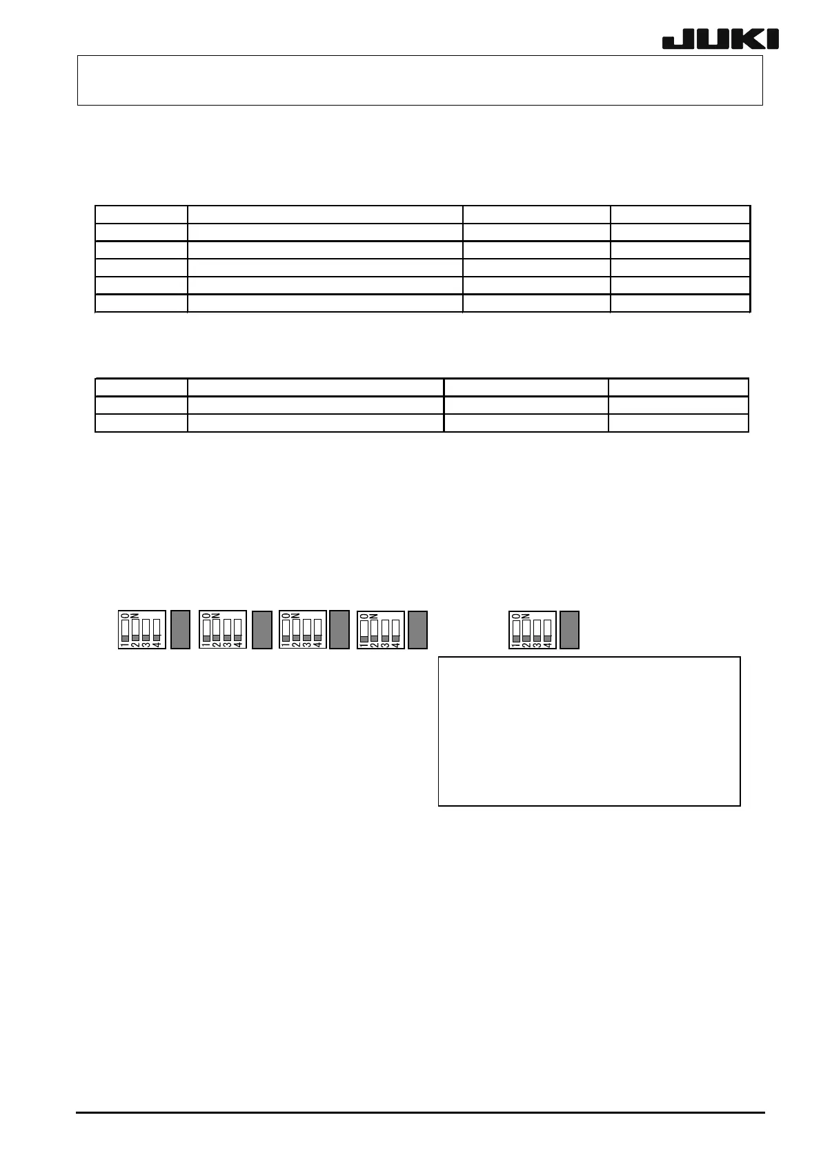
The jumper switches and DIP switches on the CONVEYOR board assembly used in the transport
unit have already been set at delivery. However, check that they are set as shown below before
setting the CARRY board assembly in the transport unit.
W3 W4 W5 W6 W7SW5 SW4 SW3 SW2 SW1
The shaded areas in the figure indicate:
(1) for DIP switches, the direction to which
is to be set, or
(2) for headers, the portion to which a
jumper is to be installed.
The following describes how to set up each jumper switch and DIP-switch. For machines other
than those having the special specifications, always use the above settings.
W1 IN MOTOR Brake time setting * Setting is not needed.
1-2 Basic clock x 7
3-4 Basic clock x 6
5-6 Basic clock x 5
7-8 Basic clock x 4
9-10 Basic clock x 3 Pattern is short-circuited.
W2 OUT MOTOR Brake time setting * Setting is not needed.
1-2 Basic clock x 7
3-4 Basic clock x 6
5-6 Basic clock x 5
7-8 Basic clock x 4
9-10 Basic clock x 3 Pattern is short-circuited.
13-28
Rev. 2.00