FX-1/FX-1R Maintenance Manual
5-8. Replacing the WAIT Sensor and C OUT 2 Sensor
5-8-1. Replacing the Fiber
(1) Detach the fiber from the WAIT sensor
amplifier. Loosen the fixing set screw to
detach the light receiving fiber.
(2) Detach the light receiving fiber from the
WAIT sensor block.
(3) Detach the light emission fiber from the
WAIT sensor bracket.
(4) When installing new fibers, reassemble the
components in the order of step (3) to (1).
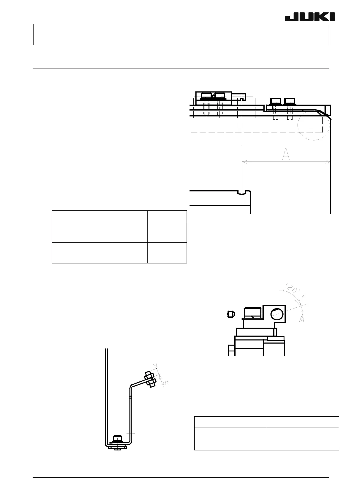
(5) When installing new fibers, make the
adjustment so that the projection amount A
from the WAIT sensor block becomes that
shown in the Table below.
5-10
Reference, Flow RAIL PLATE FL RAIL PLATE FR
Figure 5-8-1-1
WAIT Sensor Block
Table 5-8-1-1
Projection amount from sensor block
Figure 5-8-1-1 Sensor block
Front reference, Left → Right
Rear reference, Right → Left
WAIT sensor
50mm
C OUT 2 sensor
5mm
Front reference, Right → Left
Rear reference, Left → Right
C OUT 2 sensor
5mm
WAIT sensor
50mm
(6) Additionally, adjust the projection amount from
br 4 e top
w). ension
1.)
Figure 5-8-1-2
WAIT Sensor Bracket (L size)
the WAIT sensor acket to 1 mm (to th
end of the side vie (Dim B)
(7) After the fibers have been replaced, adjust the
amplifier gain as described in 5-9-2-2, How to
mount the amplifier unit. (See page 5-1
For the C OUT 2 sensor, apply the same
procedures as described above.
Figure 5-8-1-3 Sensor Block
Table 5-8-1-2
Part name Part No.
WAIT SENSOR ASM L828E9210A0
C-OUT2 SENSOR A 0A0 SM L832E721
Rev. 2.00