FX-1/FX-1R Maintenance Manual
DSW3
This switch is used to set the function Rev. and pattern Rev. of the board.
The following shows the weight of each bit.
1: Function Rev 2
0
2: Function Rev 2
1
3: Function Rev 2
2
4: Function Rev 2
3
5: Pattern function Rev 2
0
6: Pattern function Rev 2
1
7: Pattern function Rev 2
2
8: Pattern function Rev 2
3
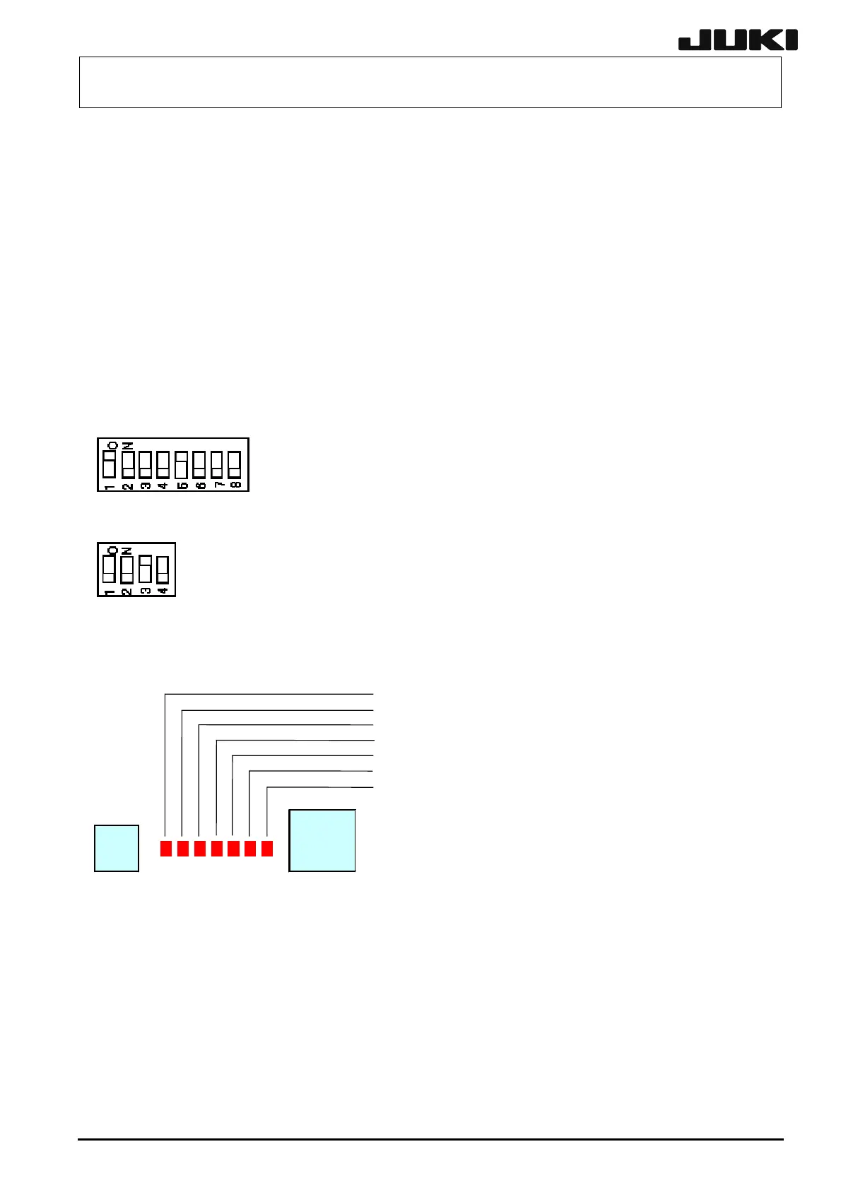
The following shows the setting example that the function Rev. is set at “01” and the pattern Rev. is
set at “01”.
DSW4
Turn on 3 only. This switch is used with only switch 3 set at ON. Do not change the switch settings.
(2) Meaning of LED
LD1: Not defined.
LD2: For checking of XY movable Z-height (Possible when lit.)
LD3: For checking of nozzle 1 deceleration sensor (Detected when lit.)
LD4: For checking of nozzle 2 deceleration sensor (Detected when lit.)
LD5: For checking of nozzle 3 deceleration sensor (Detected when lit.)
LD6: For checking of nozzle 4 deceleration sensor (Detected when lit.)
LD7: Not used.
VR8
CN8
The LEDs have the meanings described above.
13-34
Rev. 2.00
 Loading...


